V tomto článku se pokusíme rozšířit možnosti ovládání programů s pomocí infračerveného přenosu dat. Použijeme jednoduchý infračervený ovládací pult a infračervený přijímač a budeme dálkově ovládat náš program, který běží na Raspberry Pi Pico. Protokol používaný v infračerveném dálkovém ovládání je poněkud složitější, takže si nevystačíme s programováním GPIO, ale budeme muset použít PIO koprocesor. Infračervené světlo obvykle používané v dálkových ovladačích má vlnovou délku \(\lambda=940 nm\). Vysílač je infračervená LED a přijímačem je infračervená fotodioda.
Infračervený vysílač
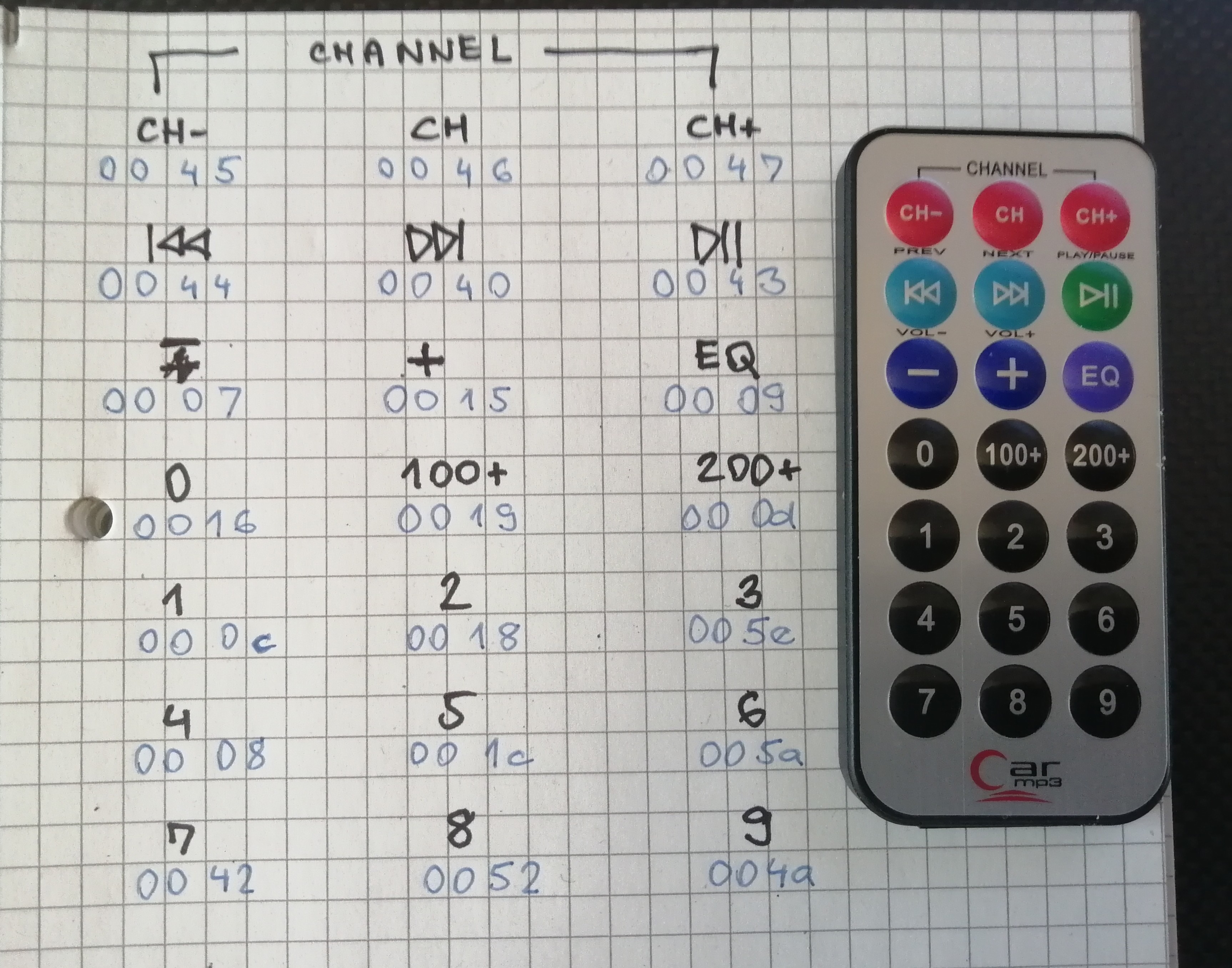
Dálkový ovladač používá k přenosu dat NEC protokol.
| Ne všechny dálkové ovladače používají NEC protokol. Přenosových protokolů v IR ovladačích je spousta. Například: APPLE, DENON, JVC, LG, LG2, NEC2, ONKYO, PANASONIC, KASEIKYO, RC5, RC6, RC6A, SAMSUNG, SHARP, SONY a další. Popis těchto protokolů je dobře dokumentován v knihovně pro Arduino Arduino IRremote |
NEC protokol
Modulace
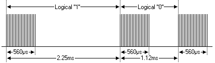
Protokol NEC používá kódování bitů s pulzní vzdáleností. Každý puls je 560 µs dlouhý nosný signál s frekvencí 38 kHz (přibližně 21 cyklů). Přenos logické „1“ trvá 2,25 ms, zatímco přenos logické „0“ trvá pouze polovinu této doby, tedy 1,125 ms. Doporučený pracovní cyklus (střída) nosné je 1/4 nebo 1/3.
Protokol
Protokol používá dva pojmy: adresa (ta bude u všech ovladačů pro konkrétní zařízení jednoho výrobce stejná) a příkaz — to je kód konkrétního stisknutého tlačítka na ovladači.
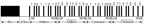
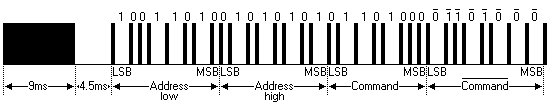
Obrázek nahoře ukazuje typický sled impulsů protokolu NEC.
U tohoto protokolu se jako první vysílá LSB (nejméně významny bit).
V tomto případě se vysílá adresa 0x59 a příkaz 0x16.
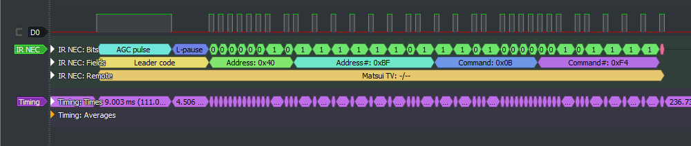
Zpráva je zahájena 9ms dávkou (burst) AGC, který se používal k nastavení zisku starších IR přijímačů.
Po tomto burstu AGC následuje 4,5ms mezera, po které následuje adresa a příkaz.
Adresa a příkaz se vysílají dvakrát.
Podruhé jsou všechny bity invertovány a lze je použít k ověření přijaté zprávy.
Celková doba přenosu je konstantní, protože každý bit se opakuje s invertovanou délkou.
Pokud nemáte zájem o tuto spolehlivost, můžete invertované hodnoty ignorovat nebo můžete adresu a příkaz rozšířit na 16 bitů (to používá NEC extended protokol).
Mějte na paměti, že na konci zprávy musí následovat jedna dávka o délce 560 µs navíc, aby bylo možné určit hodnotu posledního bitu.
Čas celého přenosu je vždy konstatní, protože obsahuje stejný počet jedniček a nul. Je to \(9ms + 4.5ms + (2.25ms+1.12ms)*16 + 0.56 ms = 9+4.5+36+17.62+0.56=67.68 ms\) přesně.
Opakování
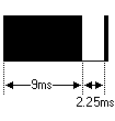
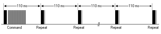
Příkaz se vyšle pouze jednou, a to i v případě, že je tlačítko na dálkovém ovladači stisknuté déle. Každých 110 ms se vysílá opakující se kód, dokud je tlačítko stisknuté. Tento opakující se kód je jednoduše 9ms impuls AGC, následovaný 2,25ms mezerou a 560µs trvající dávkou.
Rozšířený protokol NEC (Extended NEC protocol)
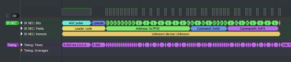
Protokol NEC je tak široce používán, že brzy byly vyčerpány všechny možné adresy. Obětováním redundance adres byl rozsah adres rozšířen z 256 možných hodnot na přibližně 65 000 různých hodnot. Tímto způsobem byl rozsah adres rozšířen z 8 bitů na 16 bitů, aniž by se změnila jakákoli jiná vlastnost protokolu. Rozšířením rozsahu adres tímto způsobem již není celkový čas zprávy konstantní. Nyní závisí na celkovém počtu jedniček a nul ve zprávě. Pokud chcete zachovat celkový čas zprávy konstantní, musíte se ujistit, že počet jedniček v adresním poli je 8 (automaticky to znamená, že počet nul je také 8). Tím se maximální počet různých adres sníží na pouhých 13 000.
Redundance příkazů je stále zachována. Každá adresa tedy stále zvládne 256 různých příkazů.
Testovací smyčka
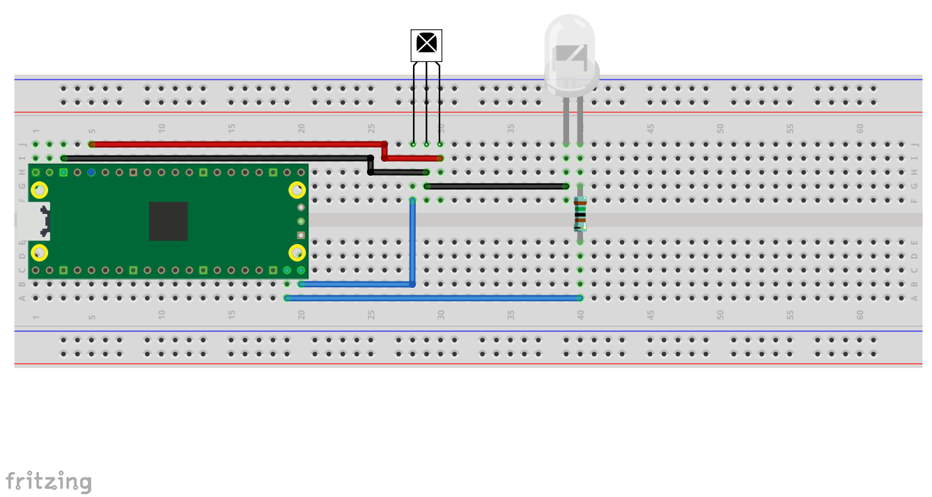
Tento příklad ukazuje, jak použít Raspberry Pi Pico (RP2040) k odesílání a přijímání infračervených snímků ve formátu 'NEC', který používá mnoho spotřebitelských aplikací pro dálkové ovládání.
Provádí se test zpětné smyčky přenosem IR kódů prostřednictvím IR LED a jejich příjmem na IR detektoru. Výsledky se odesílají na výchozí sériový terminál připojený přes UART nebo USB, jak je nakonfigurováno v SDK.
Úlohy kódování a dekódování dat jsou přesunuty na stavové automaty RP2040 PIO. Tím se uvolní hlavní jádra procesoru, aby se mohla soustředit na jiné úkoly.
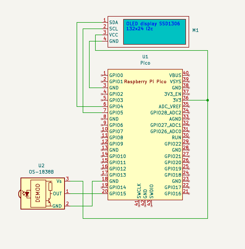
Informace o zapojení
Připojte GPIO 14 ke kladné straně („anodě“) IR LED pomocí vhodného sériového rezistoru, např. 1,5 kΩ, a zápornou stranu („katodě“) k zemi. Vlnová délka LED pravděpodobně nebude kritická, pokud je kompatibilní s vaším detektorem.
Připojte GPIO 15 k výstupu 3,3V IR detektoru, například VS1838b, a zapojte napájecí konektory detektoru na 3V3 a zem. Program očekává, že výstup dekodéru bude nízký (logická '0'), když je detekován nosný signál.
Program pro testovací smyčku najdete v pico-examples/pio/ir_nec.
- CMakeLists.txt
-
Soubor CMake pro začlenění příkladu do stromu sestavení příkladů.
- ir_loopback/CMakeLists.txt
-
Soubor CMake pro začlenění příkladu zpětné smyčky do stromu sestavení příkladů.
- ir_loopback/ir_loopback.c
-
Céčkový kód pro příklad zpětné smyčky.
- nec_receive_library/CMakeLists.txt
-
Soubor CMake pro začlenění knihovny pro příjem IR do stromu sestavení příkladů.
- nec_receive_library/nec_receive.c
-
Zdrojový kód pro funkce pro příjem IR.
- nec_receive_library/nec_receive.h
-
Hlavičkový soubor pro funkce pro příjem IR.
- nec_receive_library/nec_receive.pio
-
Kód assembleru PIO pro příjem rámce.
- nec_transmit_library/CMakeLists.txt
-
Soubor CMake pro začlenění knihovny pro přenos IR do stromu sestavení příkladů.
- nec_transmit_library/nec_transmit.c
-
Zdrojový kód pro funkce pro přenos IR.
- nec_transmit_library/nec_transmit.h
-
Hlavičkový soubor pro funkce pro přenos IR.
- nec_transmit_library/nec_carrier_burst.pio
-
Kód assembleru PIO pro generování nosné vlny.
- nec_transmit_library/nec_carrier_control.pio
-
Kód assembleru PIO pro přenos kompletního IR paketu
Konstrukce IR vysílače (RPI Pico + klávesnice)
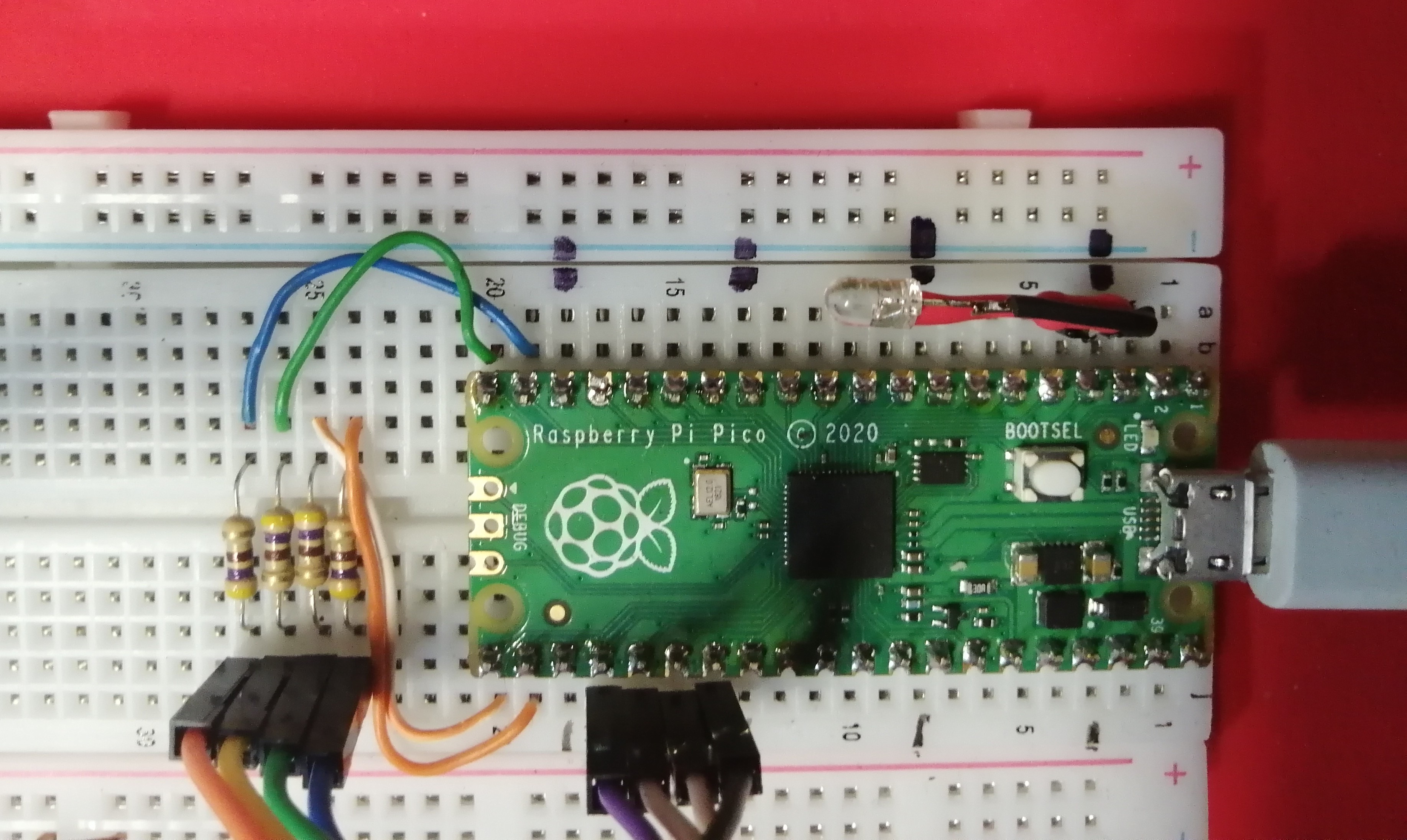
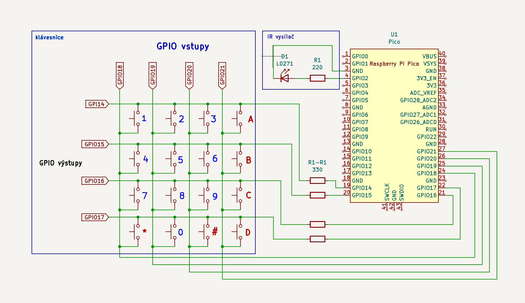
Programový kód pro maticovou klávesnici je vzat z Obsluha maticové klávesnice implementovaná pomocí PIO .ir_nec_keyboard/CMakeLists.txt
Klávesnice bude používat pio0 a posílání kódů IR bude používat pio1.
Pio program pro obsluhu klávesnice má 31 instrukcí, takže musí používat samostatný PIO (klávesnice a IR se do jednoho PIO nevejde).
ir_nec_keyboard/CMakeLists.txt
cmake_minimum_required(VERSION 3.13)

set(PICO_BOARD pico)
set(CMAKE_C_STANDARD 11)
set(CMAKE_CXX_STANDARD 17)


# initialize the SDK based on PICO_SDK_PATH
# note: this must happen before project()
include($ENV{PICO_SDK_PATH}/external/pico_sdk_import.cmake)

project(ir_keyboard C CXX ASM)

# initialize the Raspberry Pi Pico SDK
pico_sdk_init()

add_subdirectory( nec_transmit_library )
add_executable (ir_keyboard ir_keyboard.c)
pico_generate_pio_header(ir_keyboard ${CMAKE_CURRENT_LIST_DIR}/keyboard.pio)


# link the executable using the IR transmit library
#
target_link_libraries(ir_keyboard LINK_PUBLIC
  pico_stdlib
  hardware_pio
  nec_transmit_library
  )

pico_add_extra_outputs(ir_keyboard)
pico_enable_stdio_usb(ir_keyboard 1)
pico_enable_stdio_uart(ir_keyboard 0)
ir_nec_keyboard/ir_keyboard.c
/**
 * Maticová klávesnice 4x4 s přenosem IR na jiné Pico
 * ir_keyboard.c
 * Copyright (c) 2026 Jirka Chráska, <jirka@lixis.cz>
 *
 * License: BSD-3-Clause
 */

#include <stdio.h>
#include <stdlib.h>
#include "pico/stdlib.h"
#include "pico/util/queue.h"
#include "hardware/pio.h"
// knihovna pro přenos IR
#include "nec_transmit.h"
// klávesnice pomocí PIO
#include "keyboard.pio.h"

#define BASE_KEYPAD_PIN 14
#define OUT_KEYPAD_PIN  18
#define KEYROWS         4
#define NUMKEYS         16
#define FIFO_SIZE       64
#define MAX_COUNTER     10
#define IR_addr         0xac
#define IR_LED_PIN      2


static PIO ir_pio = pio0;
static uint ir_sm;

static PIO kbd_pio = pio1;
static uint kbd_sm;
static uint8_t kbd_pio_irq;
static uint kbd_offset;
static bool klavesa = false;
static queue_t fifo;

char pismeno = '\0';


static char klavesy[4][4] = {
                            '1', '2', '3', 'A',
                            '4', '5', '6', 'B',
                            '7', '8', '9', 'C',
                            '*', '0', '#', 'D'
                            };


static uint32_t tx_frame[4][4] = {
        0,0,0,0,
        0,0,0,0,
        0,0,0,0,
        0,0,0,0
};

// naplnění pole tx_frame
// zakódování jednotlivých kláves pro přenos NEC protokolem
void encode_all_keys()
{
    for(int i=0; i<4; i++) {
        for(int j=0; j<4; j++) {
            tx_frame[j][i] = nec_encode_frame(IR_addr, klavesy[i][j]);
        }
    }
}

// obsluha přerušení vyvolaná při stisku klávesy
static void pio_irq_obsluzna_funkce( void )
{
    while( !pio_sm_is_rx_fifo_empty( kbd_pio, kbd_sm ) ) {
        if( pio_sm_get_rx_fifo_level(kbd_pio, kbd_sm) == 2 ) {
            uint32_t x,y;
            x = pio_sm_get( kbd_pio, kbd_sm );
            y = pio_sm_get( kbd_pio, kbd_sm );
            int i, j;
            for( i=0; i<4; i++) {
                if( x >> i == 1) break;
            }
            for( j=0; j<4; j++) {
                if( y >> j == 1 ) break;
            }
            pismeno = klavesy[j][i];
            // odeslání IR kódu
            pio_sm_put(ir_pio, ir_sm, tx_frame[i][j]);
            klavesa = true;
        }
    }
    irq_clear(kbd_pio_irq);
}


int main()
{
    stdio_init_all();
    gpio_init(25);
    gpio_set_dir(25,true);
    gpio_put(25,1);
    sleep_ms(2000);
    gpio_put(25,0);
    printf("Klávesnice s IR vysílačem.\n");
    // protože budeme posílat IR kódy v rámci obsluhy přerušení klávesnice,
    // připravíme si dopředu zakódování, aby byla obsluha přerušení rychlá
    encode_all_keys();
    const uint tx_gpio = IR_LED_PIN;   // pin kde je IR LED

    // konfigurace a spuštění stavového PIO strojku pro IR
    ir_sm = nec_tx_init(ir_pio, tx_gpio);

    // nastavení klávesnice
    queue_init(&fifo, sizeof(uint32_t), FIFO_SIZE);
    kbd_offset = pio_add_program(kbd_pio, &keyboard_program);
    kbd_sm = pio_claim_unused_sm(kbd_pio, true);
    if (kbd_sm == -1 || ir_sm == -1) {
        printf("Nemohu nastavit PIO\n");
        return -1;
    }
    keyboard_program_init(kbd_pio, kbd_sm, kbd_offset, BASE_KEYPAD_PIN, OUT_KEYPAD_PIN);
    // najdeme volné přerušení
    kbd_pio_irq = pio_get_irq_num(kbd_pio,0);
    if( irq_get_exclusive_handler( kbd_pio_irq ) ) {
        kbd_pio_irq++;
        if( irq_get_exclusive_handler( kbd_pio_irq ) ){
            panic("Nenalezen volný interrupt.");
        }
    }
    // nastavíme přerušení pro klávesnici
    // přidáme sdílenou obsluhu
    irq_add_shared_handler(kbd_pio_irq, pio_irq_obsluzna_funkce,
                           PICO_SHARED_IRQ_HANDLER_DEFAULT_ORDER_PRIORITY);
    irq_set_enabled(kbd_pio_irq, true); // spustíme
    // obdržíme číslo přerušení
    const uint irq_index = kbd_pio_irq - pio_get_irq_num( kbd_pio, 0);
    // nastavíme pio, aby nám řekl, když je něco ve frontě
    pio_set_irqn_source_enabled( kbd_pio, irq_index,
                                 pio_get_rx_fifo_not_empty_interrupt_source(kbd_sm), true);

    // tohle je jenom test, že to funguje
    while (true) {
        if(klavesa == true) {
            gpio_put(25,1); // blikneme default LEDkou
            printf("Stisknuto '%c'\n",pismeno);
            klavesa = false;
            sleep_ms(200);
            gpio_put(25,0);
        }
        sleep_ms(100);
    }

    queue_free(&fifo);
}
ir_nec_keyboard/keyboard.pio
; klavesnice
; (c) Jirka Chráska 2025; <jirka@lixis.cz>
.program keyboard
;
;
;
.define KEYBOARD_IRQ 0
.wrap_target

nastav_radek_1:
    set pins, 1 [31]        ; nastavím 1 pro 1. řádek klávesnice
    set X, 0x1
    in pins, 4
    mov Y, isr
    jmp !Y, nastav_radek_2
    jmp rx_fifo

nastav_radek_2:
    set pins, 2 [31]        ; nastavím 1 pro 2. řádek klávesnice
    set X, 0x2
    in pins, 4
    mov Y, isr
    jmp !Y, nastav_radek_3
    jmp rx_fifo

nastav_radek_3:
    set pins, 4 [31]        ; nastavím 1 pro 3. řádek klávesnice
    set X, 0x4
    in pins, 4
    mov Y, isr
    jmp !Y, nastav_radek_4
    jmp rx_fifo

nastav_radek_4:
    set pins, 8 [31]        ; nastavím 1 pro 4. řádek klávesnice
    set X, 0x8
    in pins, 4
    mov Y, isr
    jmp !Y nastav_radek_1

rx_fifo:
    push                    ; pošlu souřadnici y (řádek)
    in X, 4 [2]
    push                    ; pošlu souřadnici x (sloupec)
    irq KEYBOARD_IRQ  rel

    wait 0 pin 0            ; čekám, až bude klávesa uvolněna
    wait 0 pin 1
    wait 0 pin 2
    wait 0 pin 3

.wrap

% c-sdk {

#include "hardware/clocks.h"
#include "hardware/gpio.h"

static inline void keyboard_program_init (PIO pio, uint sm, uint offset, uint row_pin, uint col_pin) {

    // řádkové piny jsou nastaveny jako výstupní
    //
    pio_gpio_init(pio, row_pin);
    pio_gpio_init(pio, row_pin+1);
    pio_gpio_init(pio, row_pin+2);
    pio_gpio_init(pio, row_pin+3);
    pio_sm_set_consecutive_pindirs(pio, sm, row_pin, 4, true);

    // sloupcové piny
    pio_sm_set_consecutive_pindirs(pio, sm, col_pin, 4, false);


    // Konfigurace stavového stroje
    pio_sm_config c = keyboard_program_get_default_config (offset);

    // konfigurace vstupního posuvného registru (Input Shift Register)
    sm_config_set_in_shift (&c,
                            false,       // posunujeme doprava
                            false,       // autopush je vypnut
                            32);         //


    // piny pro funkci IN
    sm_config_set_in_pins( &c, col_pin );
    // piny pro funkci SET
    sm_config_set_set_pins( &c, row_pin, 4 );

    // zvětšení fronty
    // sm_config_set_fifo_join (&c, PIO_FIFO_JOIN_RX);

    // Tik hodin stavového stroje nastavíme na 2 KHz
    float div = clock_get_hz (clk_sys) / 4000;
    sm_config_set_clkdiv (&c, div);

    // Konfiguraci šoupneme do stavového stroje
    pio_sm_init (pio, sm, offset, &c);

    // Stavový stroj spustíme
    pio_sm_set_enabled (pio, sm, true);
}
%}
Knihovna pro IR vysílač
ir_nec_keyboard/nec_transmit_library/CMakeLists.txt
# build a normal library
#
add_library(nec_transmit_library nec_transmit.c)

# invoke pio_asm to assemble the PIO state machine programs
#
pico_generate_pio_header(nec_transmit_library ${CMAKE_CURRENT_LIST_DIR}/nec_carrier_burst.pio)
pico_generate_pio_header(nec_transmit_library ${CMAKE_CURRENT_LIST_DIR}/nec_carrier_control.pio)

target_link_libraries(nec_transmit_library PRIVATE
        pico_stdlib
        hardware_pio
        )

# add the `binary` directory so that the generated headers are included in the project
#
target_include_directories (nec_transmit_library PUBLIC
	${CMAKE_CURRENT_SOURCE_DIR}
	${CMAKE_CURRENT_BINARY_DIR}
	)
ir_nec_keyboard/nec_transmit_library/nec_transmit.h
/**
 * Copyright (c) 2021 mjcross
 *
 * SPDX-License-Identifier: BSD-3-Clause
 */

#include "pico/stdlib.h"
#include "hardware/pio.h"

// public API

int nec_tx_init(PIO pio, uint pin);
uint32_t nec_encode_frame(uint8_t address, uint8_t data);
ir_nec_keyboard/nec_transmit_library/nec_transmit.c
/**
 * Copyright (c) 2021 mjcross
 *
 * SPDX-License-Identifier: BSD-3-Clause
 */


// SDK types and declarations
//
#include "pico/stdlib.h"
#include "hardware/pio.h"
#include "hardware/clocks.h"    // for clock_get_hz()
#include "nec_transmit.h"

// import the assembled PIO state machine programs
#include "nec_carrier_burst.pio.h"
#include "nec_carrier_control.pio.h"

// Claim an unused state machine on the specified PIO and configure it
// to transmit NEC IR frames on the specified GPIO pin.
//
// Returns: on success, the number of the carrier_control state machine
// otherwise -1
int nec_tx_init(PIO pio, uint pin_num) {

    // install the carrier_burst program in the PIO shared instruction space
    uint carrier_burst_offset;
    if (pio_can_add_program(pio, &nec_carrier_burst_program)) {
        carrier_burst_offset = pio_add_program(pio, &nec_carrier_burst_program);
    } else {
        return -1;
    }

    // claim an unused state machine on this PIO
    int carrier_burst_sm = pio_claim_unused_sm(pio, true);
    if (carrier_burst_sm == -1) {
        return -1;
    }

    // configure and enable the state machine
    nec_carrier_burst_program_init(pio,
                                   carrier_burst_sm,
                                   carrier_burst_offset,
                                   pin_num,
                                   38.222e3);                   // 38.222 kHz carrier

    // install the carrier_control program in the PIO shared instruction space
    uint carrier_control_offset;
    if (pio_can_add_program(pio, &nec_carrier_control_program)) {
        carrier_control_offset = pio_add_program(pio, &nec_carrier_control_program);
    } else {
        return -1;
    }

    // claim an unused state machine on this PIO
    int carrier_control_sm = pio_claim_unused_sm(pio, true);
    if (carrier_control_sm == -1) {
        return -1;
    }

    // configure and enable the state machine
    nec_carrier_control_program_init(pio,
                                     carrier_control_sm,
                                     carrier_control_offset,
                                     2 * (1 / 562.5e-6f),        // 2 ticks per 562.5us carrier burst
                                     32);                       // 32 bits per frame

    return carrier_control_sm;
}


// Create a frame in `NEC` format from the provided 8-bit address and data
//
// Returns: a 32-bit encoded frame
uint32_t nec_encode_frame(uint8_t address, uint8_t data) {
    // a normal 32-bit frame is encoded as address, inverted address, data, inverse data,
    return address | (address ^ 0xff) << 8 | data << 16 | (data ^ 0xff) << 24;
}
ir_nec_keyboard/nec_transmit_library/nec_carrier_control.pio
;
; Copyright (c) 2021 mjcross
;
; SPDX-License-Identifier: BSD-3-Clause
;
.pio_version 0 // only requires PIO version 0

.program nec_carrier_control

; Transmit an encoded 32-bit frame in NEC IR format.
;
; Accepts 32-bit words from the transmit FIFO and sends them least-significant bit first
; using pulse position modulation.
;
; Carrier bursts are generated using the nec_carrier_burst program, which is expected to be
; running on a separate state machine.
;
; This program expects there to be 2 state machine ticks per 'normal' 562.5us
; burst period.
;
.define BURST_IRQ 7                     ; the IRQ used to trigger a carrier burst
.define NUM_INITIAL_BURSTS 16           ; how many bursts to transmit for a 'sync burst'

.wrap_target
    pull                                ; fetch a data word from the transmit FIFO into the
                                        ; output shift register, blocking if the FIFO is empty

    set X, (NUM_INITIAL_BURSTS - 1)     ; send a sync burst (9ms)
long_burst:
    irq BURST_IRQ
    jmp X-- long_burst

    nop [15]                            ; send a 4.5ms space
    irq BURST_IRQ [1]                   ; send a 562.5us burst to begin the first data bit

data_bit:
    out X, 1                            ; shift the least-significant bit from the OSR
    jmp !X burst                        ; send a short delay for a '0' bit
    nop [3]                             ; send an additional delay for a '1' bit
burst:
    irq BURST_IRQ                       ; send a 562.5us burst to end the data bit

jmp !OSRE data_bit                      ; continue sending bits until the OSR is empty

.wrap                                   ; fetch another data word from the FIFO


% c-sdk {
static inline void nec_carrier_control_program_init (PIO pio, uint sm, uint offset, float tick_rate, int bits_per_frame) {

    // create a new state machine configuration
    //
    pio_sm_config c = nec_carrier_control_program_get_default_config(offset);

    // configure the output shift register
    //
    sm_config_set_out_shift (&c,
                             true,       // shift right
                             false,      // disable autopull
                             bits_per_frame);

    // join the FIFOs to make a single large transmit FIFO
    //
    sm_config_set_fifo_join (&c, PIO_FIFO_JOIN_TX);

    // configure the clock divider
    //
    float div = clock_get_hz (clk_sys) / tick_rate;
    sm_config_set_clkdiv (&c, div);

    // apply the configuration to the state machine
    //
    pio_sm_init(pio, sm, offset, &c);

    // set the state machine running
    //
    pio_sm_set_enabled(pio, sm, true);
}
%}
ir_nec_keyboard/nec_transmit_library/nec_carrier_burst.pio
;
; Copyright (c) 2021 mjcross
;
; SPDX-License-Identifier: BSD-3-Clause
;
.pio_version 0 // only requires PIO version 0

.program nec_carrier_burst

; Generate bursts of carrier.
;
; Repeatedly wait for an IRQ to be set then clear it and generate 21 cycles of
; carrier with 25% duty cycle
;
.define NUM_CYCLES 21               ; how many carrier cycles to generate
.define BURST_IRQ 7                 ; which IRQ should trigger a carrier burst
.define public TICKS_PER_LOOP 4     ; the number of instructions in the loop (for timing)

.wrap_target
    set X, (NUM_CYCLES - 1)         ; initialise the loop counter
    wait 1 irq BURST_IRQ            ; wait for the IRQ then clear it
cycle_loop:
    set pins, 1                     ; set the pin high (1 cycle)
    set pins, 0 [1]                 ; set the pin low (2 cycles)
    jmp X--, cycle_loop             ; (1 more cycle)
.wrap


% c-sdk {
static inline void nec_carrier_burst_program_init(PIO pio, uint sm, uint offset, uint pin, float freq) {
    // Create a new state machine configuration
    //
    pio_sm_config c = nec_carrier_burst_program_get_default_config (offset);

    // Map the SET pin group to one pin, namely the `pin`
    // parameter to this function.
    //
    sm_config_set_set_pins (&c, pin, 1);

    // Set the GPIO function of the pin (connect the PIO to the pad)
    //
    pio_gpio_init (pio, pin);

    // Set the pin direction to output at the PIO
    //
    pio_sm_set_consecutive_pindirs (pio, sm, pin, 1, true);

    // Set the clock divider to generate the required frequency
    //
    float div = clock_get_hz (clk_sys) / (freq * nec_carrier_burst_TICKS_PER_LOOP);
    sm_config_set_clkdiv (&c, div);

    // Apply the configuration to the state machine
    //
    pio_sm_init (pio, sm, offset, &c);

    // Set the state machine running
    //
    pio_sm_set_enabled (pio, sm, true);
}
%}
Infračervený přijímač
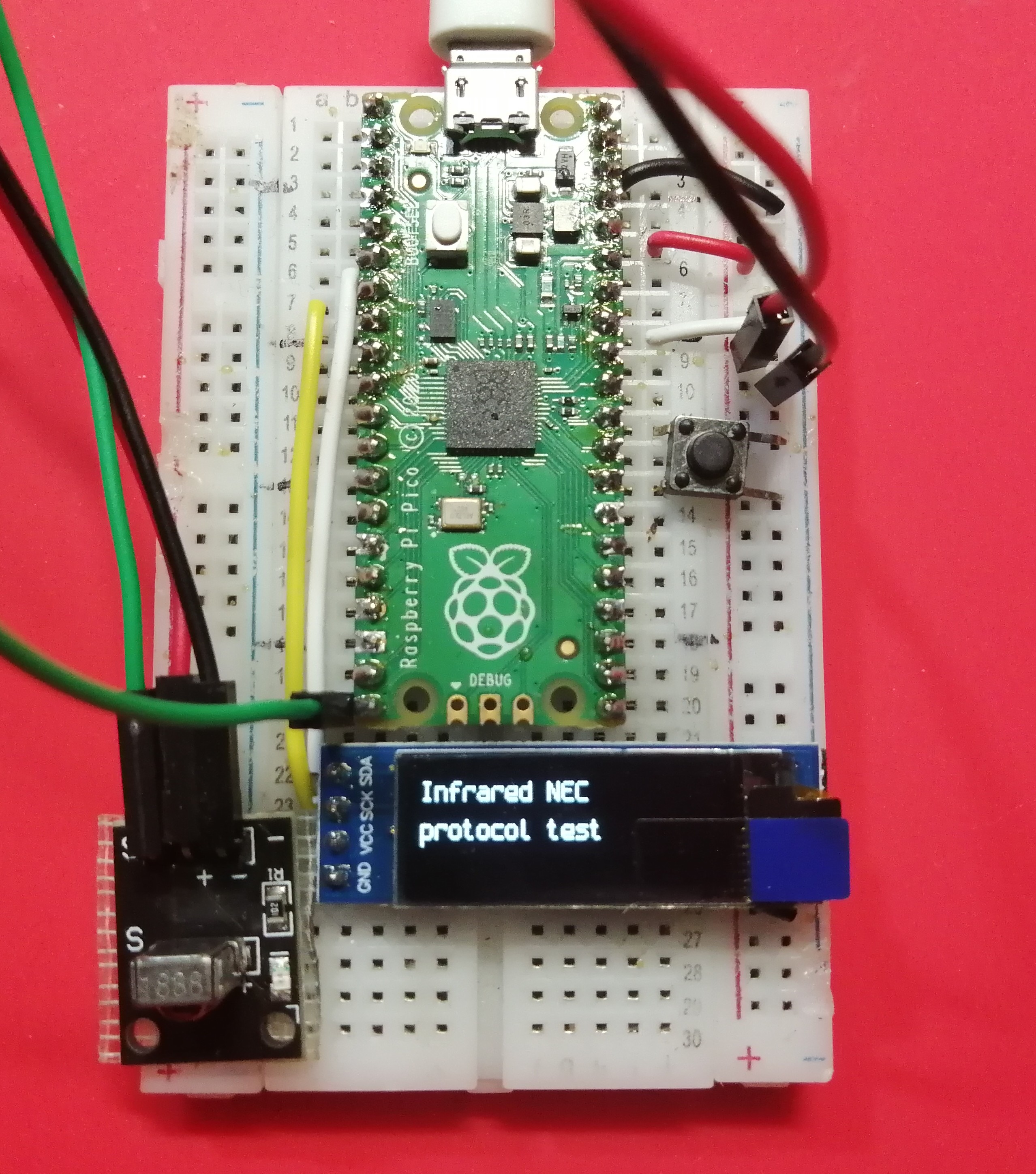
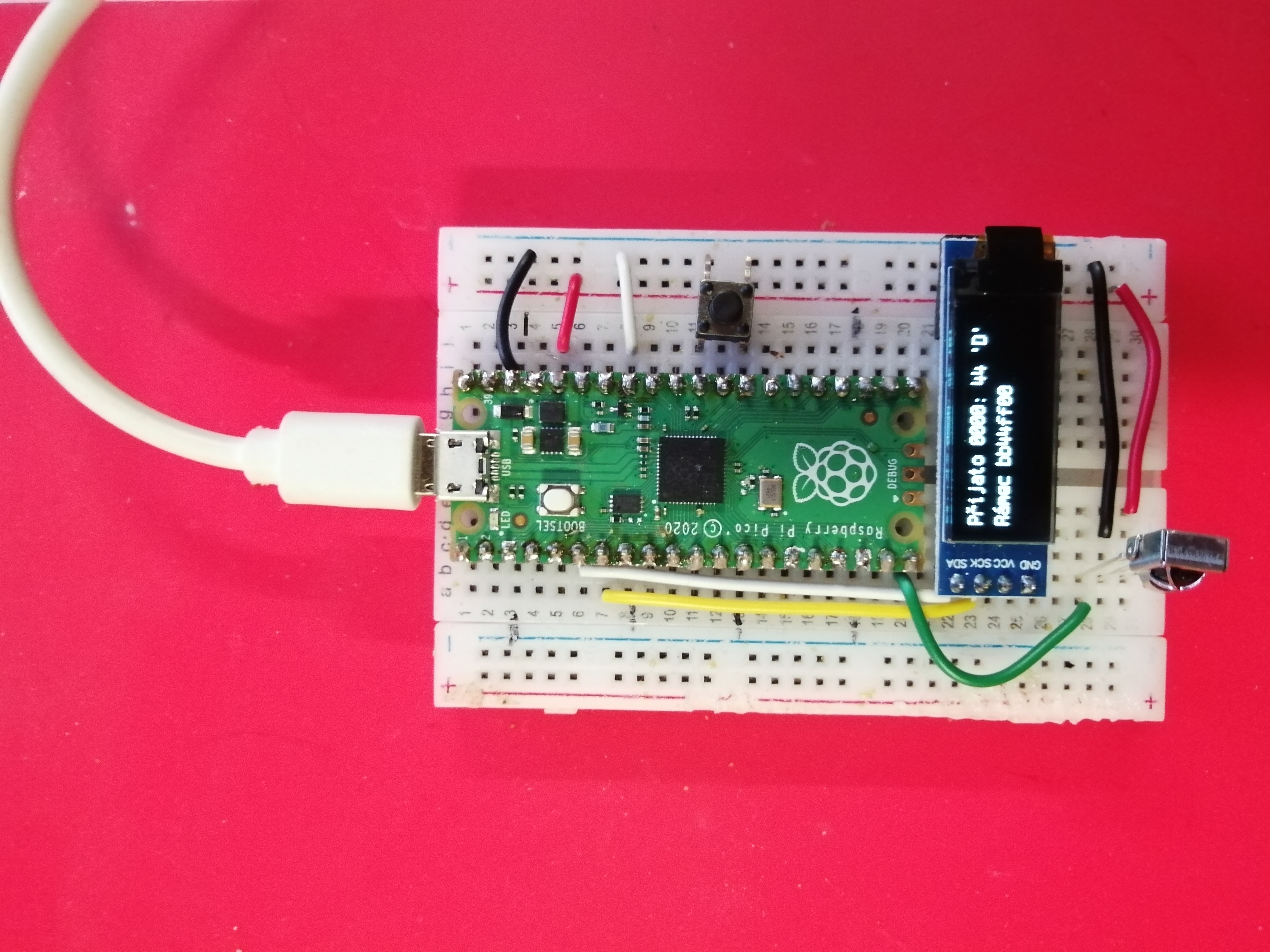
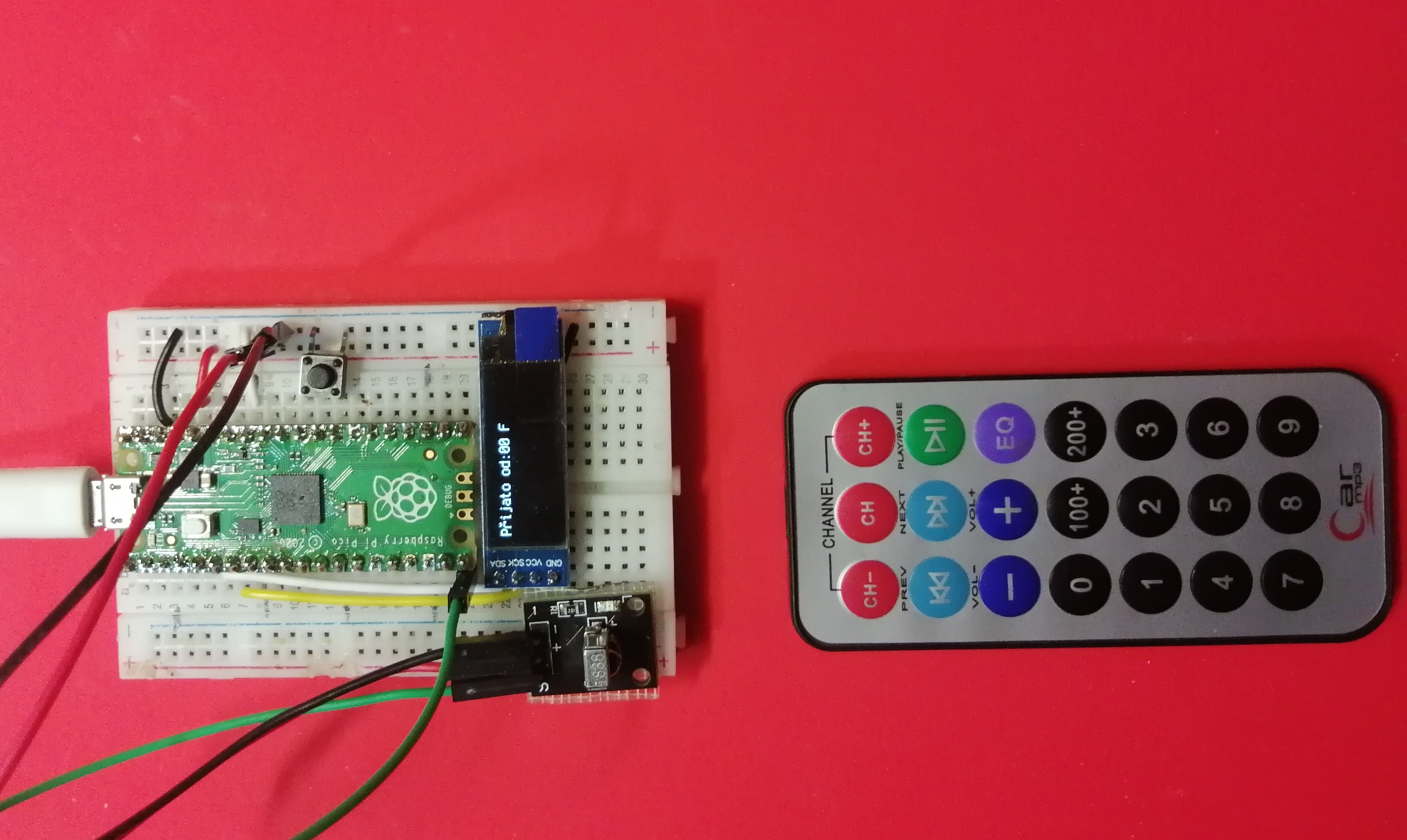
Přijímač s OLED displejem SSD1306

ir_nec_recv/CMakeLists.txt
cmake_minimum_required(VERSION 3.13)

set(PICO_BOARD pico)
set(CMAKE_C_STANDARD 11)
set(CMAKE_CXX_STANDARD 17)


# initialize the SDK based on PICO_SDK_PATH
# note: this must happen before project()
include($ENV{PICO_SDK_PATH}/external/pico_sdk_import.cmake)
# knihovna pro OLED displej SSD1306
include($ENV{LIB_SSD1306_UTF8_PATH}/pico_lib_ssd1306_utf8_import.cmake)

project(ir_receiver C CXX ASM)


# initialize the Raspberry Pi Pico SDK
pico_sdk_init()

add_subdirectory( nec_receive_library )
add_executable (ir_receiver ir_receiver.c)

target_include_directories(ir_receiver PRIVATE
    ${CMAKE_CURRENT_LIST_DIR}
    ${ssd1306_utf8_SOURCE_DIR}/src
)

# link the executable using the IR receive and ssd1306_utf libraries
#
target_link_libraries(ir_receiver LINK_PUBLIC
  pico_stdlib
  hardware_pio
  hardware_i2c
  nec_receive_library
  ssd1306_utf8
  )

pico_add_extra_outputs(ir_receiver)
pico_enable_stdio_usb(ir_receiver 1)
pico_enable_stdio_uart(ir_receiver 0)
ir_nec_recv/ir_receiver.c
/**
 * Infrared přijímač
 * Copyright (c) 2026 Jirka Chráska, <jirka@lixis.cz>
 *
 * SPDX-License-Identifier: BSD-3-Clause
 */

#include <stdio.h>
#include <string.h>
#include "pico/stdlib.h"
// knihovna pro příjem IR dat NEC protokolem
#include "nec_receive.h"

// pro OLED displej SSD1306
#include "ssd1306.h"
#include "font.h"
#define DISPLAY_WIDTH   128			// šířka displeje
#define DISPLAY_HEIGHT  32			// výška displeje
#define I2C_ADDRESS     0x3C		// i2c adresa
#define I2C_FREQ        2000000		// rychlost i2c sběrnice
// rychlost i2c sběrnice může být až 2000000
#define SDA_PIN         4			// datový pin
#define SDC_PIN         5			// hodinový pin
#define I2C             i2c0		// i2c hardware

// struktura pro OLED displej včetně framebufferu
static ssd1306_t disp;
extern bitmapFONT font_spleen_6x12;

// nastavení I2C sběrnice
void setup_i2c(void)
{
    i2c_init(I2C, I2C_FREQ);
    gpio_set_function(SDA_PIN, GPIO_FUNC_I2C);
    gpio_set_function(SDC_PIN, GPIO_FUNC_I2C);
    gpio_pull_up(SDA_PIN);
    gpio_pull_up(SDC_PIN);
    // pauza 200ms je nutná kvůli displeji. Pokud není, displej se někdy nerozsvítí
    // pauza 100ms je málo
    sleep_ms(200);
}

// inicializace displeje
void zapnuti_displeje( void )
{
    ssd1306_init(&disp, DISPLAY_WIDTH, DISPLAY_HEIGHT, I2C_ADDRESS, I2C);
    ssd1306_poweron(&disp); // zapnutí displeje
    ssd1306_clear(&disp);   // vymazání displeje
    ssd1306_contrast(&disp,0x50);
    ssd1306_draw_utf8_string(&disp, 0,  0, &font_spleen_6x12, "Přijímač pro IR NEC");
    ssd1306_draw_utf8_string(&disp, 0, 16, &font_spleen_6x12, "protokol (i extended)");
    ssd1306_show(&disp); // zobrazíme na displeji
}


int main()
{
char buf[128];
char buf2[128];

    stdio_init_all();

    memset(buf,0,sizeof(buf));
    memset(buf,0,sizeof(buf2));
	// nastavení displeje SSD1306
    setup_i2c();
    zapnuti_displeje();

    PIO pio = pio0;           // výběr PIO (RP2040 má dva: pio0 a pio1)
    uint rx_gpio = 15;        // GPIO pin kde je připojen IR detektor

    // konfigurace a spuštění stavového PIO strojku
    int rx_sm = nec_rx_init(pio, rx_gpio);  // používá 1 SM a 9 instrukcí
    if (rx_sm == -1) {
        printf("Nemohu nakonfigurovat PIO\n");
        return -1;
    }

    // příjem dat
    uint16_t rx_address;
    uint8_t rx_data;
    while (true) {
        memset(buf,0,sizeof(buf));
        memset(buf,0,sizeof(buf2));

        // zobrazení přijatých dat z fronty
        while (!pio_sm_is_rx_fifo_empty(pio, rx_sm)) {
            uint32_t rx_frame = pio_sm_get(pio, rx_sm);
            sprintf(buf2, "Rámec %08x", rx_frame);
            if (nec_decode_frame_ext(rx_frame, &rx_address, &rx_data)) {
                printf("received: F: %08x A: %04x, C: %02x\n", rx_frame, rx_address, rx_data);
                sprintf(buf, "Přijato %04x: %02x '%c'", rx_address,
                        rx_data, rx_data>=0x20?rx_data:' ');
            } else {
                printf("received: ERROR %08x\n", rx_frame);
                sprintf(buf, "Chyba protokolu", rx_frame);
            }
            ssd1306_clear(&disp);
            ssd1306_draw_utf8_string(&disp, 0, 0, &font_spleen_6x12, buf);
            ssd1306_draw_utf8_string(&disp, 0,16, &font_spleen_6x12, buf2);
            ssd1306_show(&disp);
        }
        sleep_ms(900);
    }
}
Knihovna pro IR přijímač
ir_nec_recv/nec_receive_library/CMakeLists.txt
# build a normal library
#
add_library(nec_receive_library nec_receive.c)

# invoke pio_asm to assemble the state machine program
#
pico_generate_pio_header(nec_receive_library ${CMAKE_CURRENT_LIST_DIR}/nec_receive.pio)

target_link_libraries(nec_receive_library PRIVATE
        pico_stdlib
        hardware_pio
        )

# add the `binary` directory so that the generated headers are included in the project
#
target_include_directories (nec_receive_library PUBLIC
	${CMAKE_CURRENT_SOURCE_DIR}
	${CMAKE_CURRENT_BINARY_DIR}
	)
ir_nec_recv/nec_receive_library/nec_receive.h
/**
 * Copyright (c) 2021 mjcross
 *
 * SPDX-License-Identifier: BSD-3-Clause
 */

#include "pico/stdlib.h"
#include "hardware/pio.h"

// public API

int nec_rx_init(PIO pio, uint pin);
bool nec_decode_frame(uint32_t sm, uint8_t *p_address, uint8_t *p_data);
bool nec_decode_frame_ext(uint32_t sm, uint16_t *p_address, uint8_t *p_data);
ir_nec_recv/nec_receive_library/nec_receive.c
/**
 * Copyright (c) 2021 mjcross
 *
 * SPDX-License-Identifier: BSD-3-Clause
 */

// SDK types and declarations
#include "pico/stdlib.h"
#include "hardware/pio.h"
#include "hardware/clocks.h"    // for clock_get_hz()

#include "nec_receive.h"

// import the assembled PIO state machine program
#include "nec_receive.pio.h"

// Claim an unused state machine on the specified PIO and configure it
// to receive NEC IR frames on the given GPIO pin.
//
// Returns: the state machine number on success, otherwise -1
int nec_rx_init(PIO pio, uint pin_num) {

    // disable pull-up and pull-down on gpio pin
    gpio_disable_pulls(pin_num);

    // install the program in the PIO shared instruction space
    uint offset;
    if (pio_can_add_program(pio, &nec_receive_program)) {
        offset = pio_add_program(pio, &nec_receive_program);
    } else {
        return -1;      // the program could not be added
    }

    // claim an unused state machine on this PIO
    int sm = pio_claim_unused_sm(pio, true);
    if (sm == -1) {
        return -1;      // we were unable to claim a state machine
    }

    // configure and enable the state machine
    nec_receive_program_init(pio, sm, offset, pin_num);

    return sm;
}


// Validate a 32-bit frame and store the address and data at the locations
// provided.
//
// Returns: `true` if the frame was valid, otherwise `false`
bool nec_decode_frame(uint32_t frame, uint8_t *p_address, uint8_t *p_data) {

    // access the frame data as four 8-bit fields
    //
    union {
        uint32_t raw;
        struct {
            uint8_t address;
            uint8_t inverted_address;
            uint8_t data;
            uint8_t inverted_data;
        };
    } f;

    f.raw = frame;

    // a valid (non-extended) 'NEC' frame should contain 8 bit
    // address, inverted address, data and inverted data
    if (f.address != (f.inverted_address ^ 0xff) ||
        f.data != (f.inverted_data ^ 0xff)) {
        return false;
    }

    // store the validated address and data
    *p_address = f.address;
    *p_data = f.data;

    return true;
}

// Validate a 32-bit frame and store the address and data at the locations
// provided. Validate both normal and extended NEC protocol.
// added by Jirka Chráska
// Returns: `true` if the frame was valid, otherwise `false`
bool nec_decode_frame_ext(uint32_t frame, uint16_t *p_address, uint8_t *p_data) {

    // access the frame data as four 8-bit fields
    //
    union {
        uint32_t raw;
        struct {
            uint8_t address;
            uint8_t inverted_address;
            uint8_t data;
            uint8_t inverted_data;
        };
    } f;

    f.raw = frame;

    // a valid (non-extended) 'NEC' frame should contain 8 bit
    // address, inverted address, data and inverted data
    if (f.address == (f.inverted_address ^ 0xff) &&
        f.data == (f.inverted_data ^ 0xff)) {
        // store the validated address and data
        *p_address = (uint16_t) f.address;
        *p_data = f.data;
        return true;
    }
    // a valid extended 'NEC' frame should contain 16 bit
    // address, data and inverted data
    if ( f.data == (f.inverted_data ^ 0xff)) {
        *p_address = (uint16_t) f.address << 8 | f.inverted_address;
        *p_data = f.data;
        return true;
    }
    return false;
}
ir_nec_recv/nec_receive_library/nec_receive.pio
;
; Copyright (c) 2021 mjcross
;
; SPDX-License-Identifier: BSD-3-Clause
;
.pio_version 0 // only requires PIO version 0

.program nec_receive

; Decode IR frames in NEC format and push 32-bit words to the input FIFO.
;
; The input pin should be connected to an IR detector with an 'active low' output.
;
; This program expects there to be 10 state machine clock ticks per 'normal' 562.5us burst period
; in order to permit timely detection of start of a burst. The initialisation function below sets
; the correct divisor to achieve this relative to the system clock.
;
; Within the 'NEC' protocol frames consists of 32 bits sent least-siginificant bit first; so the
; Input Shift Register should be configured to shift right and autopush after 32 bits, as in the
; initialisation function below.
;
.define BURST_LOOP_COUNTER 30                   ; the detection threshold for a 'frame sync' burst
.define BIT_SAMPLE_DELAY 15                     ; how long to wait after the end of the burst before sampling

.wrap_target

next_burst:
    set X, BURST_LOOP_COUNTER
    wait 0 pin 0                                ; wait for the next burst to start

burst_loop:
    jmp pin data_bit                            ; the burst ended before the counter expired
    jmp X-- burst_loop                          ; wait for the burst to end

                                                ; the counter expired - this is a sync burst
    mov ISR, NULL                               ; reset the Input Shift Register
    wait 1 pin 0                                ; wait for the sync burst to finish
    jmp next_burst                              ; wait for the first data bit

data_bit:
    nop [ BIT_SAMPLE_DELAY - 1 ]                ; wait for 1.5 burst periods before sampling the bit value
    in PINS, 1                                  ; if the next burst has started then detect a '0' (short gap)
                                                ; otherwise detect a '1' (long gap)
                                                ; after 32 bits the ISR will autopush to the receive FIFO
.wrap


% c-sdk {
static inline void nec_receive_program_init (PIO pio, uint sm, uint offset, uint pin) {

    // Set the GPIO function of the pin (connect the PIO to the pad)
    //
    pio_gpio_init(pio, pin);

    // Set the pin direction to `input` at the PIO
    //
    pio_sm_set_consecutive_pindirs(pio, sm, pin, 1, false);

    // Create a new state machine configuration
    //
    pio_sm_config c = nec_receive_program_get_default_config (offset);

    // configure the Input Shift Register
    //
    sm_config_set_in_shift (&c,
                            true,       // shift right
                            true,       // enable autopush
                            32);        // autopush after 32 bits

    // join the FIFOs to make a single large receive FIFO
    //
    sm_config_set_fifo_join (&c, PIO_FIFO_JOIN_RX);

    // Map the IN pin group to one pin, namely the `pin`
    // parameter to this function.
    //
    sm_config_set_in_pins (&c, pin);

    // Map the JMP pin to the `pin` parameter of this function.
    //
    sm_config_set_jmp_pin (&c, pin);

    // Set the clock divider to 10 ticks per 562.5us burst period
    //
    float div = clock_get_hz (clk_sys) / (10.0 / 562.5e-6);
    sm_config_set_clkdiv (&c, div);

    // Apply the configuration to the state machine
    //
    pio_sm_init (pio, sm, offset, &c);

    // Set the state machine running
    //
    pio_sm_set_enabled (pio, sm, true);
}
%}
ir_nec_recv/nec_receive_library/nec_receive_repeat.pio
;
; Copyright (c) 2021 mjcross
;
; SPDX-License-Identifier: BSD-3-Clause
;
.pio_version 0 // only requires PIO version 0

.program nec_receive

; Decode IR frames in NEC format and push 32-bit words to the input FIFO.
;
; The input pin should be connected to an IR detector with an 'active low' output.
;
; This program expects there to be 10 state machine clock ticks per 'normal' 562.5us burst period
; in order to permit timely detection of start of a burst. The initialisation function below sets
; the correct divisor to achieve this relative to the system clock.
;
; Within the 'NEC' protocol frames consists of 32 bits sent least-siginificant bit first; so the
; Input Shift Register should be configured to shift right and autopush after 32 bits, as in the
; initialisation function below.
;
.define BURST_LOOP_COUNTER 30                   ; the detection threshold for a 'frame sync' burst
.define BIT_SAMPLE_DELAY 15                     ; how long to wait after the end of the burst before sampling

.wrap_target

next_burst:
    set X, BURST_LOOP_COUNTER
    wait 0 pin 0                                ; wait for the next burst to start

burst_loop:
    jmp pin data_bit                            ; the burst ended before the counter expired
    jmp X-- burst_loop                          ; wait for the burst to end

                                                ; the counter expired - this is a sync burst
    mov ISR, NULL                               ; reset the Input Shift Register
    wait 1 pin 0                                ; wait for the sync burst to finish
    jmp next_burst                              ; wait for the first data bit

data_bit:
    nop [ BIT_SAMPLE_DELAY - 1 ]                ; wait for 1.5 burst periods before sampling the bit value
    in PINS, 1                                  ; if the next burst has started then detect a '0' (short gap)
                                                ; otherwise detect a '1' (long gap)
                                                ; after 32 bits the ISR will autopush to the receive FIFO
.wrap


% c-sdk {
static inline void nec_receive_program_init (PIO pio, uint sm, uint offset, uint pin) {

    // Set the GPIO function of the pin (connect the PIO to the pad)
    //
    pio_gpio_init(pio, pin);

    // Set the pin direction to `input` at the PIO
    //
    pio_sm_set_consecutive_pindirs(pio, sm, pin, 1, false);

    // Create a new state machine configuration
    //
    pio_sm_config c = nec_receive_program_get_default_config (offset);

    // configure the Input Shift Register
    //
    sm_config_set_in_shift (&c,
                            true,       // shift right
                            true,       // enable autopush
                            32);        // autopush after 32 bits

    // join the FIFOs to make a single large receive FIFO
    //
    sm_config_set_fifo_join (&c, PIO_FIFO_JOIN_RX);

    // Map the IN pin group to one pin, namely the `pin`
    // parameter to this function.
    //
    sm_config_set_in_pins (&c, pin);

    // Map the JMP pin to the `pin` parameter of this function.
    //
    sm_config_set_jmp_pin (&c, pin);

    // Set the clock divider to 10 ticks per 562.5us burst period
    //
    float div = clock_get_hz (clk_sys) / (10.0 / 562.5e-6);
    sm_config_set_clkdiv (&c, div);

    // Apply the configuration to the state machine
    //
    pio_sm_init (pio, sm, offset, &c);

    // Set the state machine running
    //
    pio_sm_set_enabled (pio, sm, true);
}
%}
Konstrukce
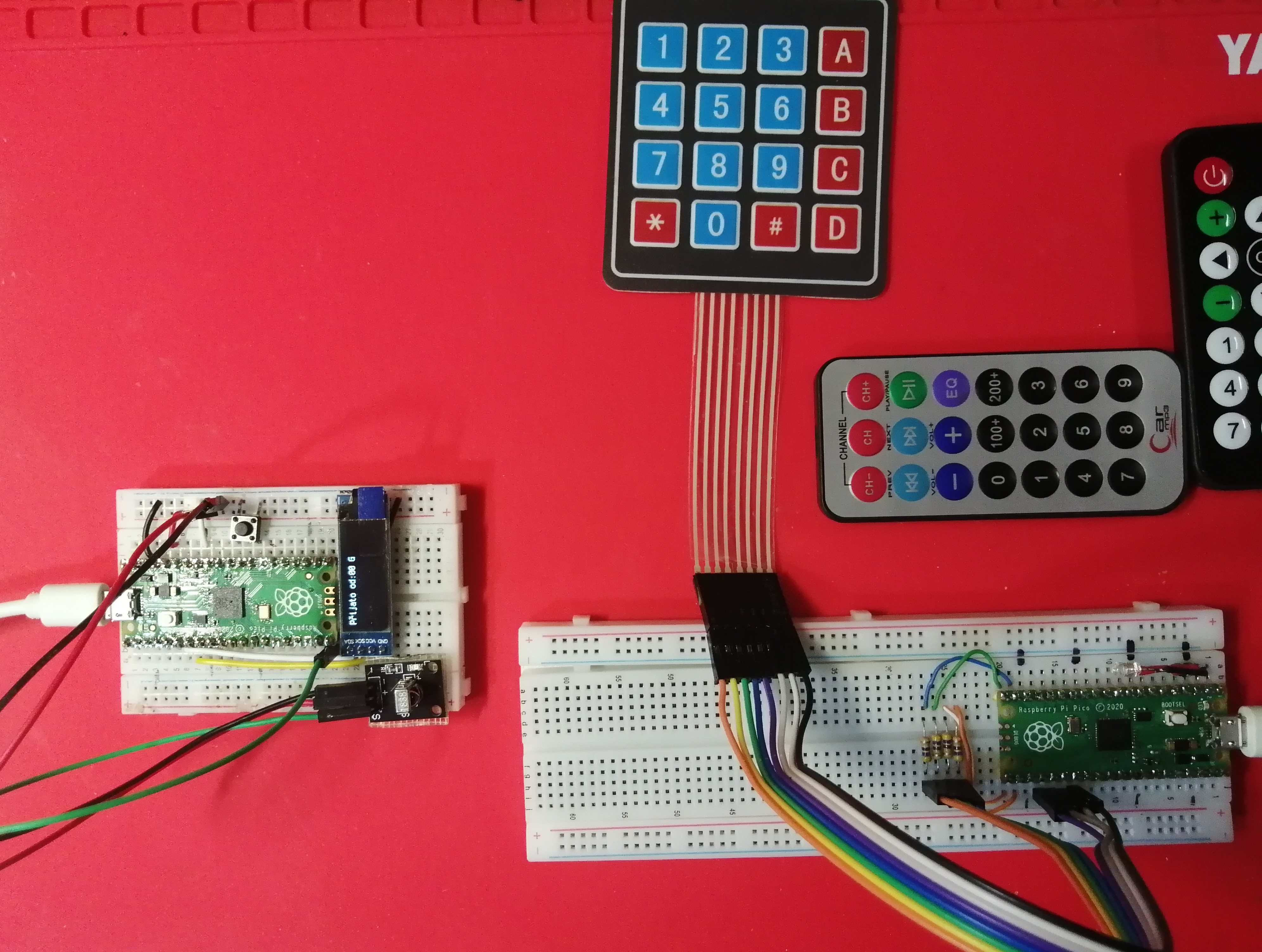
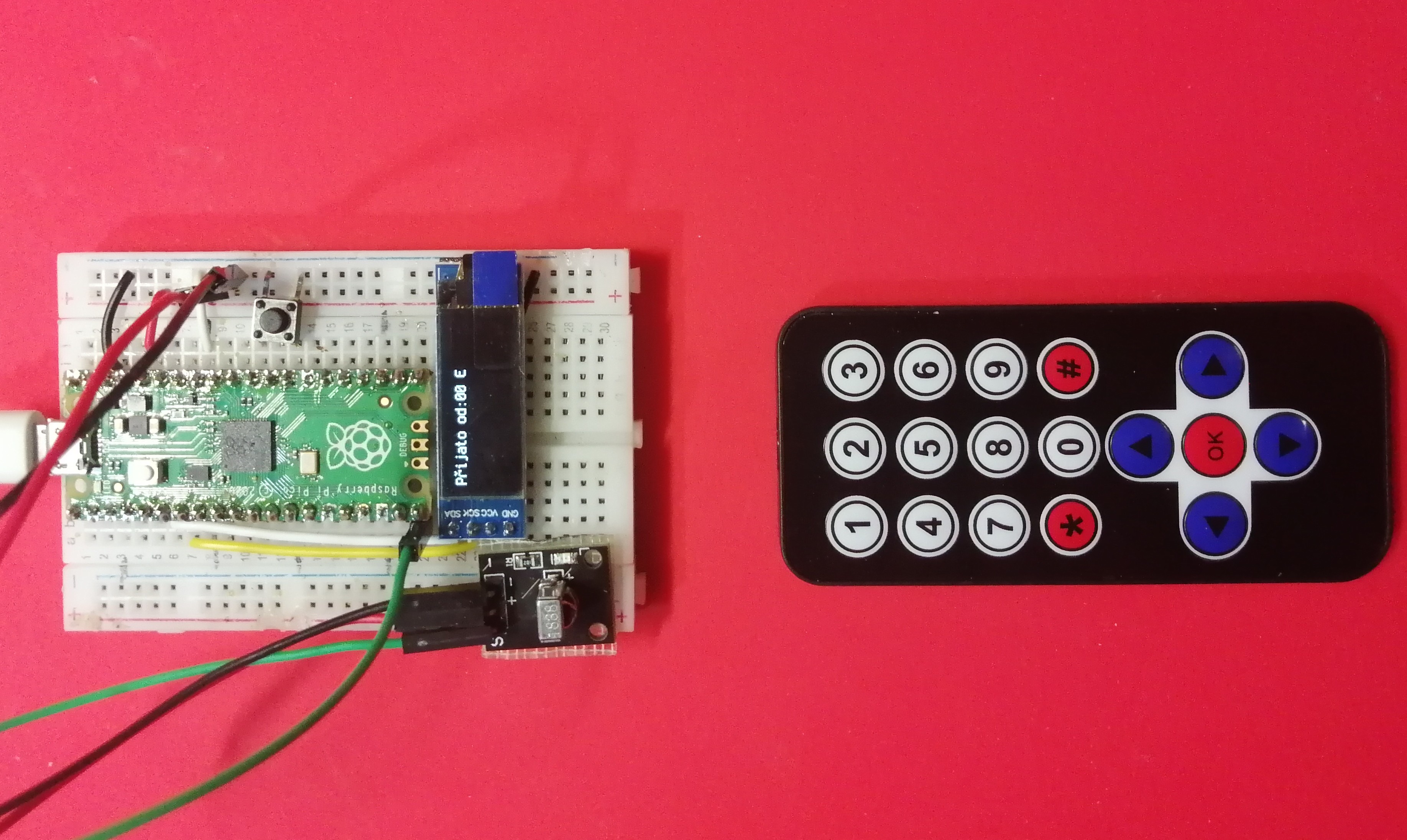
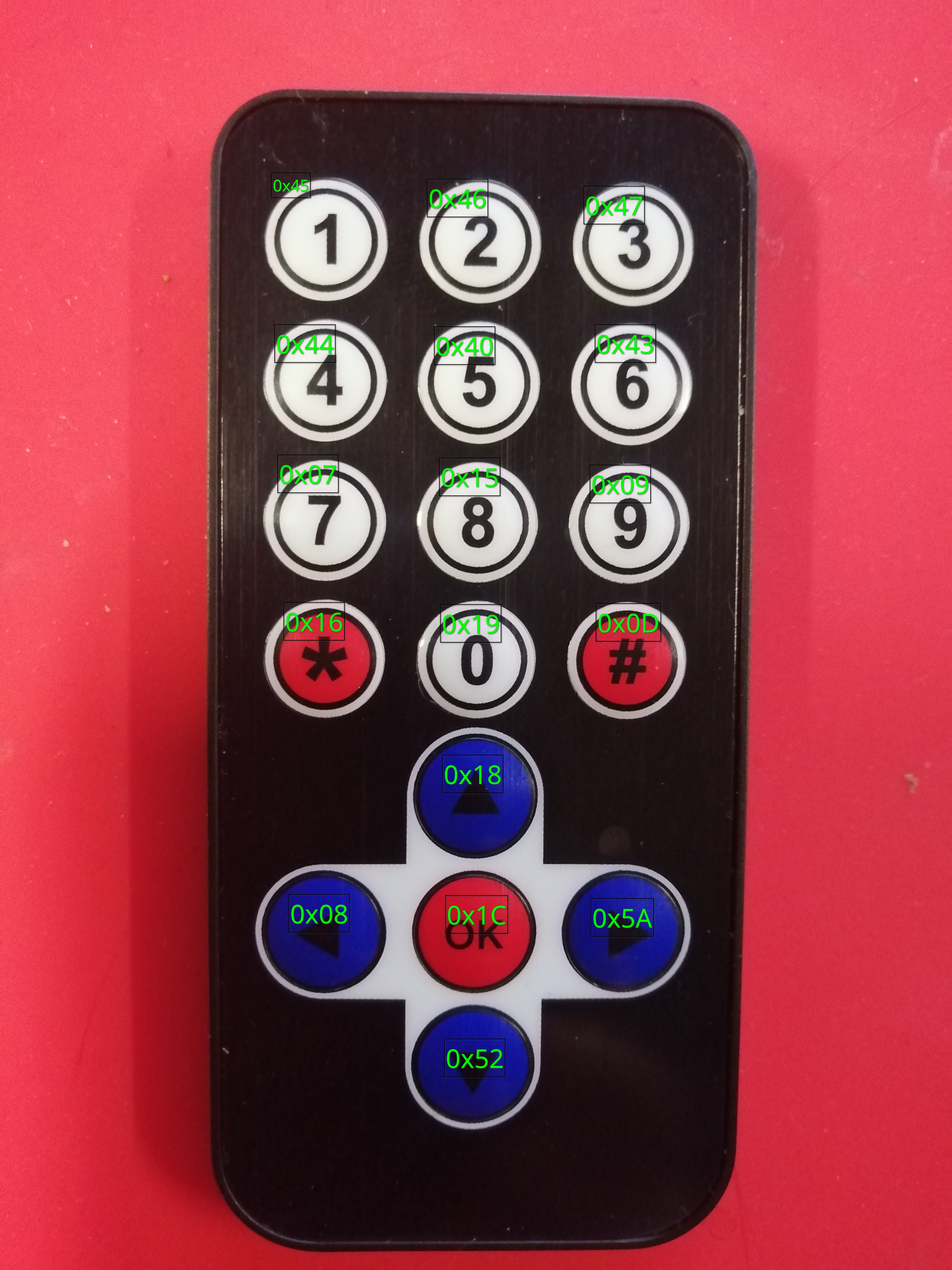
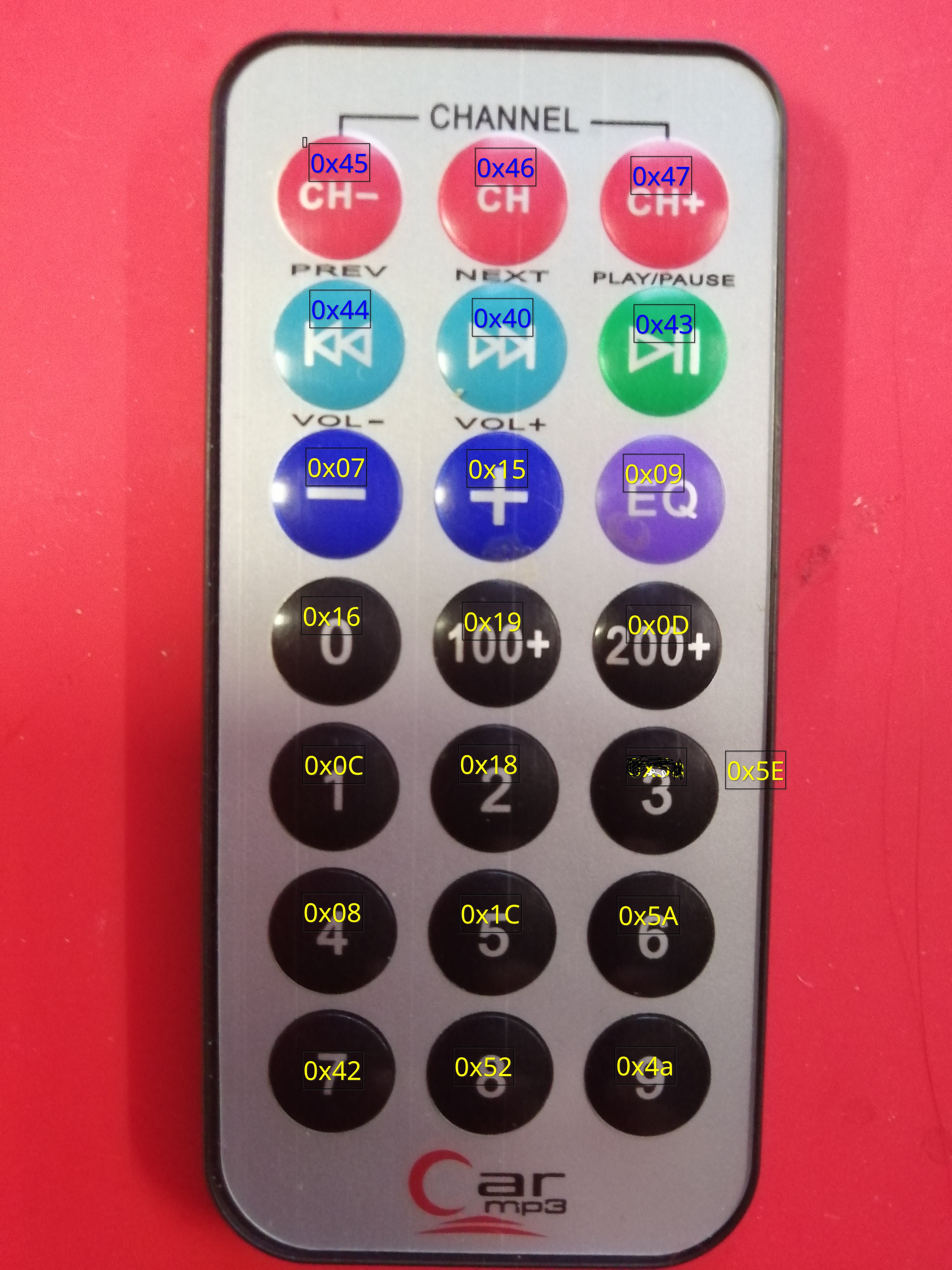
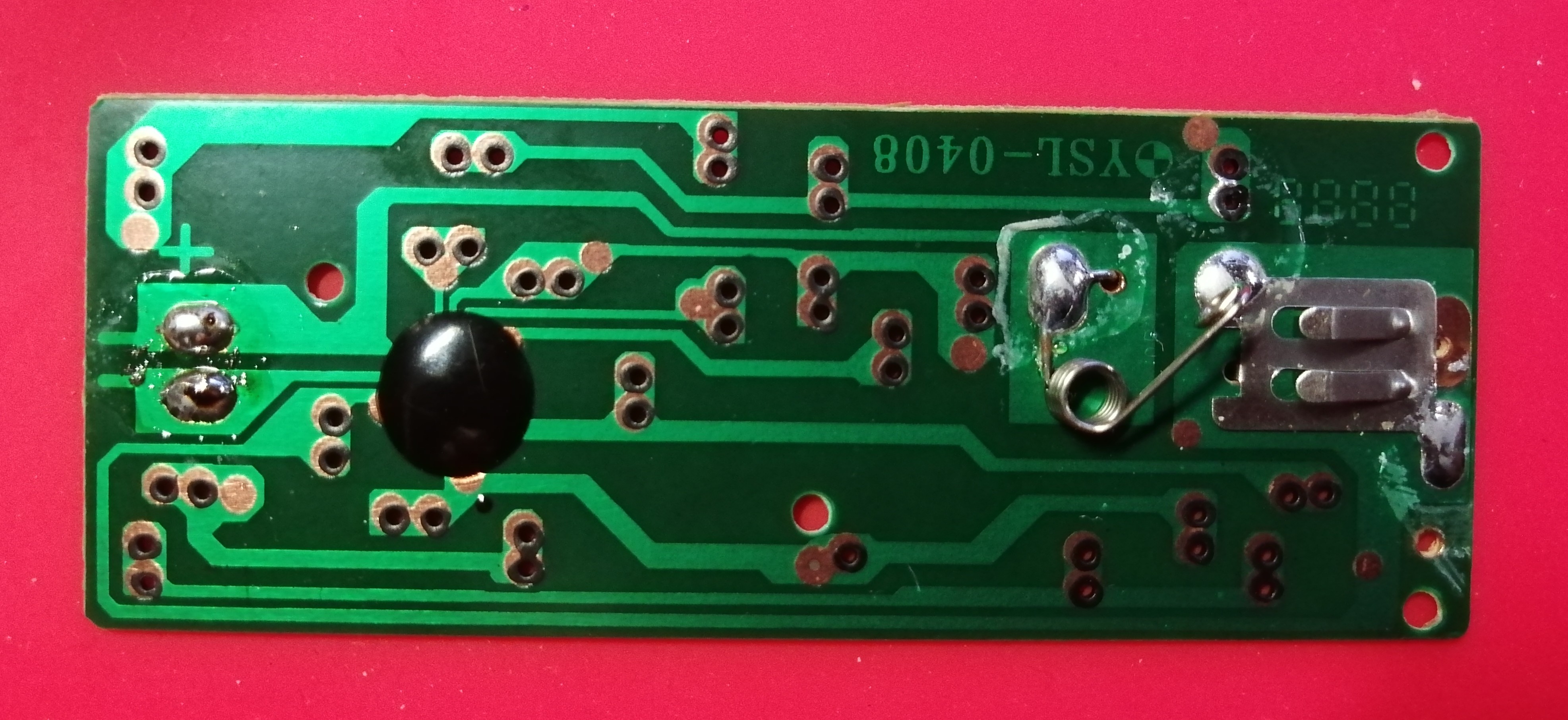
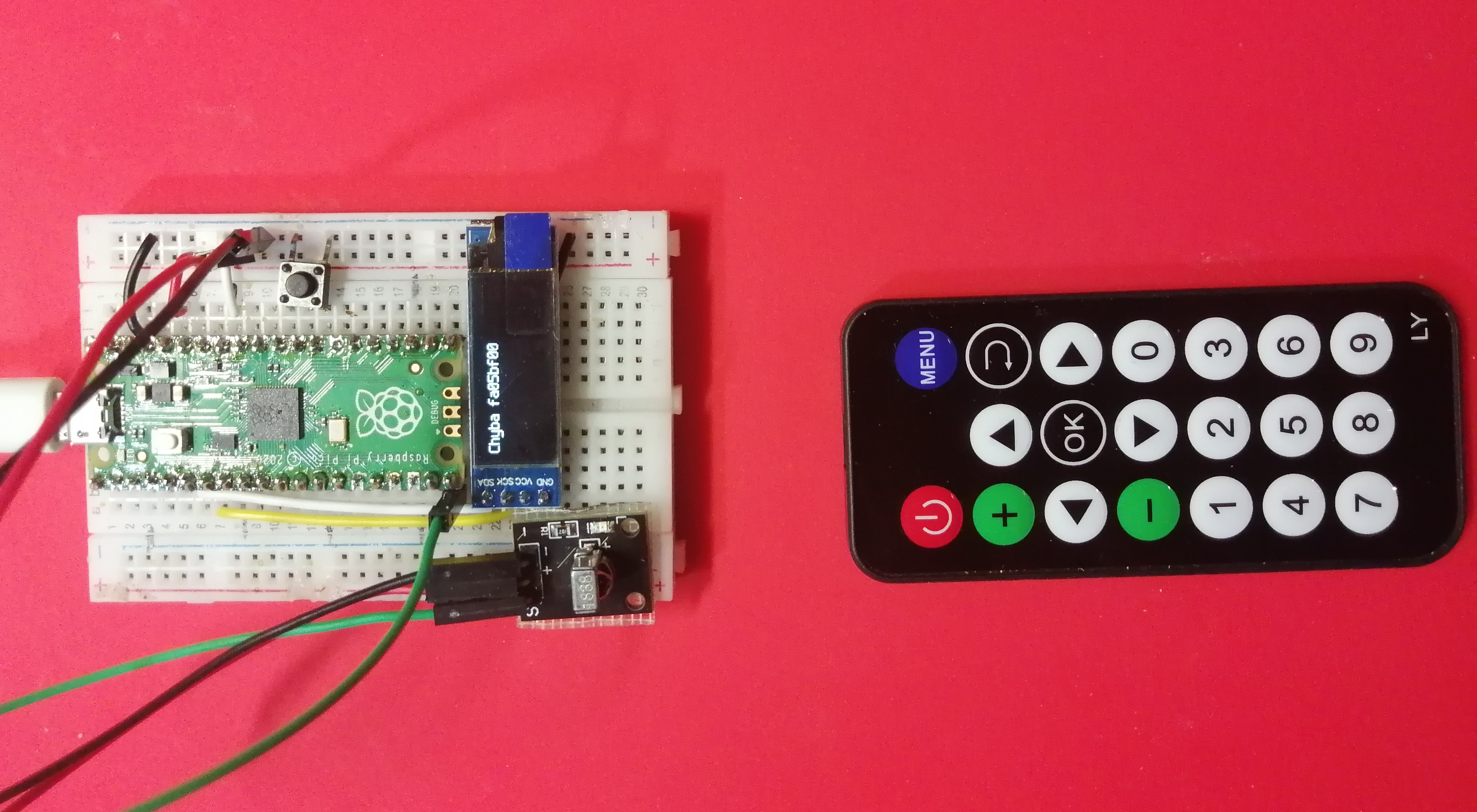
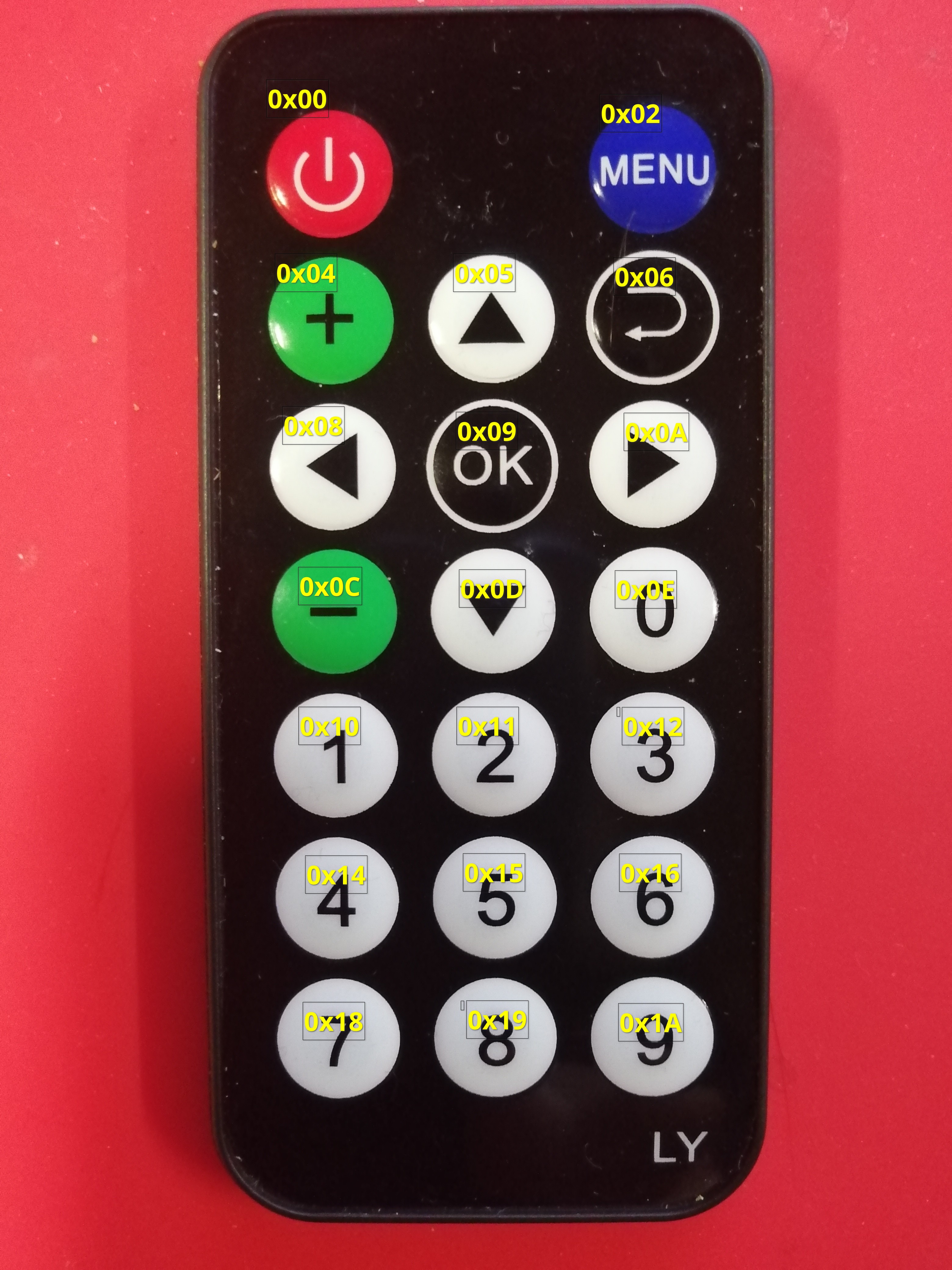
Problém komerčních ovladačů spočívá v tom, že nelze změnit adresu ovladače (je obvykle nastavena navrdo na 0x00) ani měnit posílaná data (což tolik nevadí). Kódy, které posílají jednotlivá tlačítka si můžeme snadno zjistit pomocí IR přijímače.
Zdroje a odkazy
Datový list IR přijímače vs1838b — IR čidlo z Laskakitu
Infrared IR Remote Control Controller Set For Arduino — velmi podrobné informace o IR protokolech
NEC Protocol — popis NEC protokolu