Uděláme pomocí Raspberry Pi Pico jednoduchou "VGA kartu" s rozlišením 640x468 pixelů a 16 barvami. Je to vylepšení předchozího řešení s 8 barvami. Doplníme některé další věci: pěkný font Spleen 8x16 a zápis textů na obrazovku. Rošíření na 16 barev uděláme tak, že přidáme další informaci k zelené barvě. Zelená barva teď bude reprezentována dvěma bity a bude mít 4 stavy.
Jak je to naprogramované
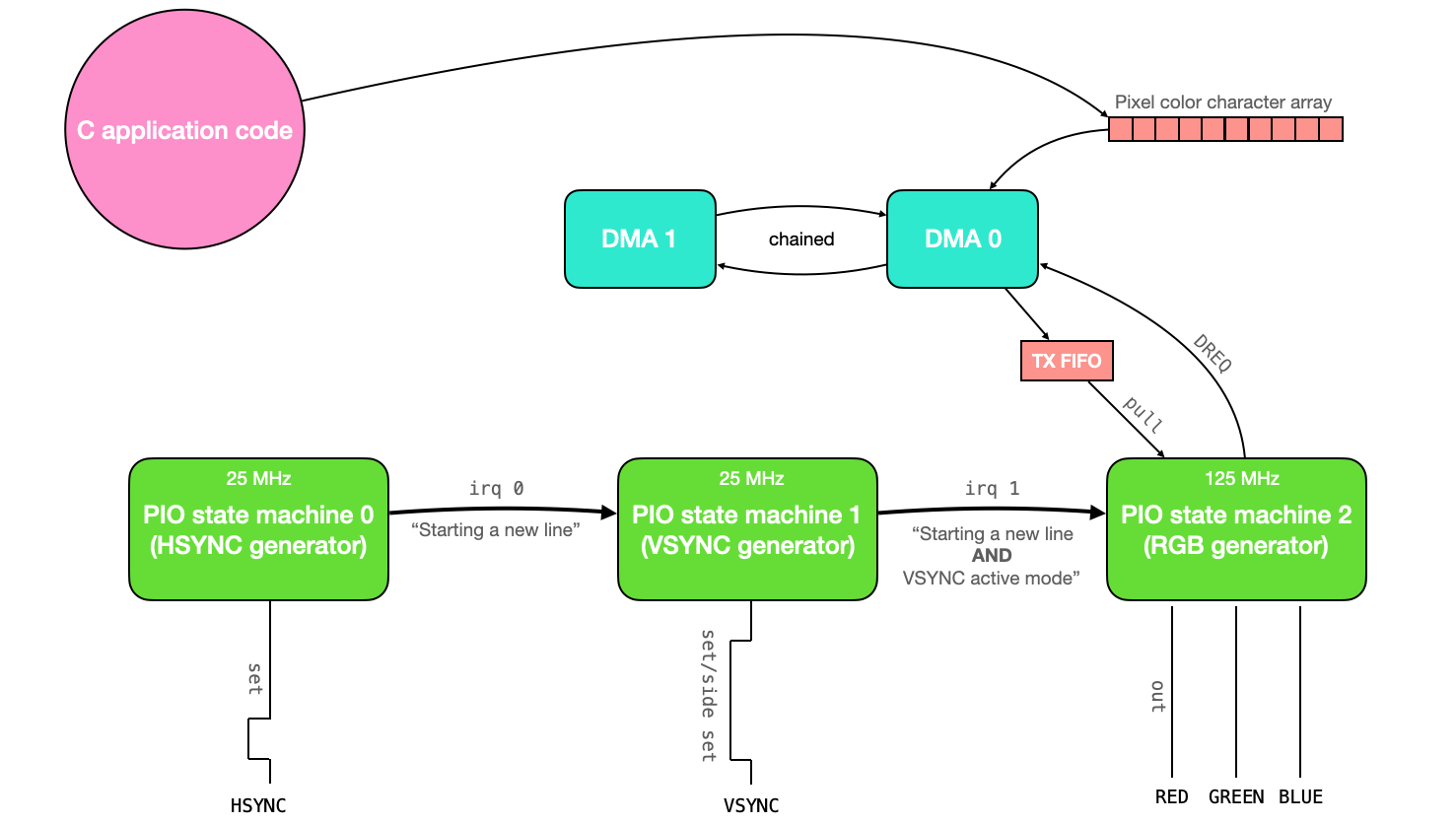
Tento kód používá tři stavové automaty PIO (synchronizované navzájem pomocí přerušení) k řízení obrazovky VGA. Data pixelů, která se mají vykreslit na obrazovku, jsou do stavových automatů PIO přenášena prostřednictvím kanálu DMA. Všechna tato data pixelů jsou uložena v globálním poli znaků. V aplikační části kódu tedy uživatel stačí upravit obsah tohoto globálního pole znaků a změny se automaticky zobrazí na obrazovce VGA.
Co se týče zdrojů, tento kód používá stavové automaty PIO 0, 1 a 2 na instanci PIO 0. Používá všech 32 dostupných instrukcí PIO a používá 2 kanály DMA (jeden pro přenos dat do systému PIO a druhý pro rekonfiguraci a restart prvního). Pro uložení barevných dat pro každý pixel se používají pouze 3 bity, což znamená, že na obrazovku lze vykreslit pouze 8 barev. Protože pro reprezentaci barvy v každém pixelu se používají pouze 3 bity, každý znak v poli znaků ukládá data pro 2 pixely (a 2 z 8 bitů se ztratí). To dává celkové využití paměti 1,536 kB.
Tento dokument vysvětluje kód ovladače VGA a poté jej používá k vykreslení Mandelbrotovy množiny na obrazovku.
Protokol VGA
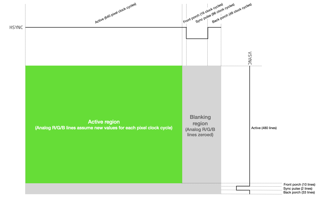
Řízení obrazovky VGA vyžaduje manipulaci se dvěma digitálními synchronizačními piny a třemi analogovými barevnými piny (ČERVENÁ, ZELENÁ a MODRÁ). Jeden ze synchronizačních pinů, HSYNC, říká obrazovce, kdy se má přesunout na nový řádek pixelů. Druhý synchronizační pin, VSYNC, říká obrazovce, kdy má začít nový snímek. Protokol je popsán níže, a to jak textově, tak vizuálně.
-
VGA pixelový takt běží na 25,172 MHz (na mé VGA obrazovce si vystačím s 25 MHz).
-
HSYNC i VSYNC začínají v aktivním režimu (logická úroveň vysoká).
-
HSYNC zůstává v aktivním režimu po dobu 640 cyklů pixelových taktů (tj. jeden řádek displeje VGA).
-
Pro každý z 640 cyklů se napětí na linkách ČERVENÁ, ZELENÁ a MODRÁ mění mezi 0 a 0,7 V, přičemž každé napětí představuje intenzitu dané barvy pro daný pixel.
-
Po 640 taktovacích cyklech se linky ČERVENÁ, ZELENÁ a MODRÁ nastaví na 0 a linka HSYNC zůstává vysoká po celou dobu svého předního pulzu (16 taktovacích cyklů pixelů).
-
HSYNC je nastaven na logickou úroveň nízkou po dobu 96 taktovacích cyklů pixelů (to je horizontální synchronizační impuls).
-
HSYNC je nastaven na logickou úroveň vysokou po dobu svého zadního pulzu (48 taktovacích cyklů pixelů).
-
HSYNC se poté vrátí na začátek aktivního režimu (krok 2 výše) a proces se opakuje pro další řádek pixelů. Každý řádek pixelů je řádek.
-
VSYNC zůstává v aktivním režimu (logická úroveň vysoká) po dobu 480 řádků.
-
Po 480 řádcích se napětí na linkách ČERVENÁ, ZELENÁ a MODRÁ nastaví na 0 a linka VSYNC zůstává vysoká po celou dobu svého předního pulzu (10 řádků).
-
VSYNC je nastaven na logickou úroveň nízkou po dobu 2 řádků (to je vertikální synchronizační impuls).
-
VSYNC je nastaven na logickou úroveň 1 až do konce (33 řádků).
-
VSYNC se poté vrátí na začátek aktivního režimu (krok 2 výše) a proces se opakuje pro další rámec.
Vytváření Hsync pulsů
Kód v PIO assembleru vytváří signál HSYNC pro VGA displej. Tento kód používá hodiny běžící na kmitočtu 25 MHz.
;
; Hunter Adams (vha3@cornell.edu)
; HSync generation for VGA driver


; Program name
.program hsync

; frontporch: 16 clocks (0.64us at 25MHz)
; sync pulse: 96 clocks (3.84us at 25MHz)
; back porch: 48 clocks (1.92us at 25MHz)
; active for: 640 clcks (25.6us at 25MHz)
;
; High for 704 cycles (28.16us at 25MHz)
; Low  for 96  cycles (3.84us at 25MHz)
; Total period of 800 cycles (32us at 25MHz)
;


pull block              ; Pull from FIFO to OSR (only happens once)
.wrap_target            ; Program wraps to here

; ACTIVE + FRONTPORCH
mov x, osr              ; Copy value from OSR to x scratch register
activeporch:
   jmp x-- activeporch  ; Remain high in active mode and front porch

; SYNC PULSE
pulse:
    set pins, 0 [31]    ; Low for hsync pulse (32 cycles)
    set pins, 0 [31]    ; Low for hsync pulse (64 cycles)
    set pins, 0 [31]    ; Low for hsync pulse (96 cycles)

; BACKPORCH
backporch:
    set pins, 1 [31]    ; High for back porch (32 cycles)
    set pins, 1 [12]    ; High for back porch (45 cycles)
    irq 0       [1]     ; Set IRQ to signal end of line (47 cycles)
.wrap


% c-sdk {
static inline void hsync_program_init(PIO pio, uint sm, uint offset, uint pin) {

    // creates state machine configuration object c, sets
    // to default configurations. I believe this function is auto-generated
    // and gets a name of <program name>_program_get_default_config
    // Yes, page 40 of SDK guide
    pio_sm_config c = hsync_program_get_default_config(offset);

    // Map the state machine's SET pin group to one pin, namely the `pin`
    // parameter to this function.
    sm_config_set_set_pins(&c, pin, 1);

    // Set clock division (div by 5 for 25 MHz state machine)
    sm_config_set_clkdiv(&c, 5) ;

    // Set this pin's GPIO function (connect PIO to the pad)
    pio_gpio_init(pio, pin);
    // pio_gpio_init(pio, pin+1);

    // Set the pin direction to output at the PIO
    pio_sm_set_consecutive_pindirs(pio, sm, pin, 1, true);

    // Load our configuration, and jump to the start of the program
    pio_sm_init(pio, sm, offset, &c);

    // Set the state machine running (commented out so can be synchronized w/ vsync)
    // pio_sm_set_enabled(pio, sm, true);
}
%}
Řádek po řádku se děje toto:
-
blok pullčeká, až kód C vloží informace do vyrovnávací paměti TX stavového automatu pio, a poté tyto informace stáhne do výstupního posuvného registru. Protože se tento řádek kódu nachází nad direktivouwrap_target, bude proveden pouze jednou. Toto se používá k uložení délky režimů active+front porch signálu HSYNC (640+16) do výstupního posuvného registru. Tuto hodnotu musíme inicializovat tímto způsobem, protože v assembleru PIO nemůžeme nastavit hodnotu žádného registru na číslo větší než 31. -
Direktiva
.wrap_targetoznačuje místo, kam se kód po dokončení zalomí. Pokud bychom neměli direktivy.wrapa.wrap_target, kód by se zalomil zpět na první řádek. -
Poté přejdeme do aktivních/předních režimů. Další řádek kódu přesune data z výstupního posuvného registru (který obsahuje délku aktivního a předního režimů) do pomocného registru
x. -
activeporchje návěští, které můžeme použít s instrukcíjmppro návrat na konkrétní místo v kódu. -
jmp x — activeporchbude snižovat hodnotu v pomocném registruxa vracet se na místo vactiveporchv kódu, dokud je hodnotaxvětší než0. Když sexrovná0, podmínkajmpselže a kód se přesune na další řádek. -
Návěští
pulseurčuje část signálu HSYNC, která se týká synchronizačního pulsu. -
Nastavíme hodnotu skupiny pinů (mapovaných samostatně na konkrétní GPIO porty) na nízkou úroveň a čekáme 31 cyklů. Všimněte si, že zpoždění začíná po provedení řádku. Takže tento řádek nastaví hodnotu pinů na nízkou úroveň a poté bude čekat dalších 31 cyklů, celkem tedy 32.
-
Znovu to uděláme to samé aby celkový čas s piny na nízké úrovni dosáhl 64 cyklů.
-
A znovu, aby celkový čas s piny na nízké úrovni dosáhl 96 cyklů (délka synchronizačního impulsu).
-
Poté vstoupíme do režimu
backporch. -
Piny jsou nastaveny na vysokou úroveň a provedeme zpoždění o 31 cyklů.
-
Piny zůstanou na vysoké úrovni a provedeme zpoždění o dalších 12 cyklů.
-
Nastavíme přerušení 0 (toto se používá k synchronizaci s assemblerovým kódem VSYNC) a provedeme zpoždění o 1 cyklus. Toto zpoždění je zde proto, aby se tento kód vrátil do aktivního režimu ve stejném cyklu jako assemblerový kód VSYNC, se kterým je synchronizován.
Takto to vypadá na osciloskopu.

Generování Vsync
Následující kód generuje VSYNC. Tento stavový automat má také hodiny běžící na 25 MHz, ale je z velké části řízen stavovým automatem HSYNC (protože VSYNC pracuje v jednotkách řádků a nikoli v pixelových hodinových cyklech).
;
; Hunter Adams (vha3@cornell.edu)
; VSync generation for VGA driver

; Program name
.program vsync
.side_set 1 opt

; frontporch: 10  lines
; sync pulse: 2   lines
; back porch: 33  lines (perhaps we try 32, since that's easier)
; active for: 480 lines
;
; Code size could be reduced with side setting


pull block                        ; Pull from FIFO to OSR (only once)
.wrap_target                      ; Program wraps to here

; ACTIVE
mov x, osr                        ; Copy value from OSR to x scratch register
activefront:
    wait 1 irq 0                  ; Wait for hsync to go high
    irq 1                         ; Signal that we're in active mode
    jmp x-- activefront           ; Remain in active mode, decrementing counter

; FRONTPORCH
set y, 9                          ;
frontporch:
    wait 1 irq 0                  ;
    jmp y-- frontporch            ;

; SYNC PULSE
set pins, 0                       ; Set pin low
wait 1 irq 0                      ; Wait for one line
wait 1 irq 0                      ; Wait for a second line

; BACKPORCH
set y, 31                         ; First part of back porch into y scratch register (and delays a cycle)
;set pins, 1                      ; Raise high for back porch (delaying a set cycle) - REPLACED WITH SIDESET
backporch:
    wait 1 irq 0   side 1         ; Wait for hsync to go high - SIDESET REPLACEMENT HERE
    jmp y-- backporch             ; Remain in backporch, decrementing counter

;wait 1 irq 0                      ; Wait for final (33rd) backporch line (eliminated)

.wrap                             ; Program wraps from here


% c-sdk {
static inline void vsync_program_init(PIO pio, uint sm, uint offset, uint pin) {

    // creates state machine configuration object c, sets
    // to default configurations. I believe this function is auto-generated
    // and gets a name of <program name>_program_get_default_config
    // Yes, page 40 of SDK guide
    pio_sm_config c = vsync_program_get_default_config(offset);

    // Map the state machine's SET pin group to one pin, namely the `pin`
    // parameter to this function.
    sm_config_set_set_pins(&c, pin, 1);
    sm_config_set_sideset_pins(&c, pin);

    // Set clock division (div by 5 for 25 MHz state machine)
    sm_config_set_clkdiv(&c, 5) ;

    // Set this pin's GPIO function (connect PIO to the pad)
    pio_gpio_init(pio, pin);
    // pio_gpio_init(pio, pin+1);

    // Set the pin direction to output at the PIO
    pio_sm_set_consecutive_pindirs(pio, sm, pin, 1, true);

    // Load our configuration, and jump to the start of the program
    pio_sm_init(pio, sm, offset, &c);

    // Set the state machine running (commented out so can be synchronized with hsync)
    // pio_sm_set_enabled(pio, sm, true);
}
%}
Řádek po řádku se děje toto:
-
pull blockčeká, až kód C vloží informace do vyrovnávací paměti TX stavového automatu pio, a poté tyto informace stáhne do výstupního posuvného registru. Protože tento řádek kódu je nad direktivou.wrap_target, bude proveden pouze jednou. Toto se používá k uložení délky aktivního režimu signálu VSYNC (480 řádků) do výstupního posuvného registru. Tuto hodnotu musíme inicializovat tímto způsobem, protože v assembleru PIO nemůžeme nastavit hodnotu žádného registru na číslo větší než 31. -
Direktiva
.wrap_targetoznačuje místo, kam se kód po dokončení zalomí (zacyklí). Pokud bychom neměli direktivy.wrapa.wrap_target, kód by se zalomil zpět na první řádek. -
Poté přejdeme do aktivního režimu. Další řádek kódu přesune data z výstupního posuvného registru (který obsahuje délku aktivního režimu) do pomocného registru
x. -
activeje návěští, které můžeme použít s instrukcíjmpk návratu na konkrétní místo v kódu. -
Stavový automat čeká na přerušení nastavené stavovým automatem HSYNC, které signalizuje konec řádku. Tato přerušení určují tempo čtení a odpočítávání řádků.
-
Pokaždé, když stavový automat HSYNC signalizuje nový horizontální řádek a stavový automat VSYNC je v aktivním režimu, nastaví samostatné přerušení. Toto přerušení používá stavový automat RGB PIO k určení, kdy začít ukládat data na piny RGB.
-
Příkaz
jmp x-- activesnižuje hodnotu v pomocném registruxa vrací se do aktivní pozice v kódu, dokud je hodnotaxvětší než0. Když sexrovná0, podmínkajmpselže a kód pokračuje na další řádek. -
Další řádek nastaví hodnotu pomocného registru
yna délku přední části signálu VSYNC (mínus 1, abychom získali celkem 10 čekání). -
Návěští
frontporchurčuje část signálu VSYNC, která se týká přední části signálu. -
Stejně jako dříve, kód používá příkazy
waitajmpk setrvání v tomto stavu, dokud stavový automat HSYNC nenastaví přerušení pro správný počet opakování. -
Nastavíme hodnotu skupiny pinů (mapovaných samostatně na specifické porty GPIO) na nízkou úroveň a poté čekáme na dokončení dvou linek HSYNC. Toto je délka synchronizačního impulsu VSYNC.
-
Poté vstupujeme do zadní části signálu. Délka zadní části signálu je uložena v pomocném registru
y. -
Stejně jako dříve používáme příkazy
waitajmpk setrvání v tomto stavu po odpovídající počet řádků.
K nastavení linky VSYNC na vysokou úroveň používáme instrukci side set místo instrukce set.
Piny set a side set jsou konfigurovány tak, aby se překrývaly, a to nám ušetří jednu instrukci.
|
Generování barevných RGB signálů
Stavový automat pro generování 25MHz RGB signálů je poměrně jednoduchý. Po určité inicializaci čítacích registrů vynuluje barevné piny, dokud neobdrží signál ze stavového automatu VSYNC, že byl spuštěn nový řádek a VSYNC je v aktivním režimu. Když je tato podmínka splněna, RGB automat ví, že by měl naprogramovat 640 pixelů (tj. jeden řádek). Dělá to tak, že provede načítání z TX FIFO (které je přiváděno k pixelovým datům z DMA kanálu), odešle první 3 bity na RGB piny, čeká na příslušný počet cyklů, odešle další 3 bity, čeká na příslušný počet cyklů, poté se vrátí zpět a opakuje to, dokud nedokončí řádek. Jakmile je řádek dokončen, vynuluje výstupy a znovu čeká na signál ze stroje VSYNC. Všimněte si, že tento stavový automat běží na 125 MHz.
;
; Hunter Adams (vha3@cornell.edu)
; RGB generation for VGA driver
; mod by Bruce Land for 16 colors

; Program name
.program rgb

pull block 					; Pull from FIFO to OSR (only once)
mov y, osr 					; Copy value from OSR to y scratch register
.wrap_target

set pins, 0 				; Zero RGB pins in blanking
mov x, y 					; Initialize counter variable

wait 1 irq 1 [3]			; Wait for vsync active mode (starts 5 cycles after execution)

colorout:
	pull block				; Pull color value
	out pins, 4	[4]			; Push out to pins (first pixel)
	out pins, 4	[2]			; Push out to pins (next pixel)
	jmp x-- colorout		; Stay here thru horizontal active mode

.wrap


% c-sdk {
static inline void rgb_program_init(PIO pio, uint sm, uint offset, uint pin) {

    // creates state machine configuration object c, sets
    // to default configurations. I believe this function is auto-generated
    // and gets a name of <program name>_program_get_default_config
    // Yes, page 40 of SDK guide
    pio_sm_config c = rgb_program_get_default_config(offset);

    // Map the state machine's SET and OUT pin group to three pins, the `pin`
    // parameter to this function is the lowest one. These groups overlap.
    sm_config_set_set_pins(&c, pin, 4);
    sm_config_set_out_pins(&c, pin, 4);

    // Set clock division (Commented out, this one runs at full speed)
    // sm_config_set_clkdiv(&c, 5) ;

    // Set this pin's GPIO function (connect PIO to the pad)
    pio_gpio_init(pio, pin);
    pio_gpio_init(pio, pin+1);
    pio_gpio_init(pio, pin+2);
    pio_gpio_init(pio, pin+3);

    // Set the pin direction to output at the PIO (3 pins)
    pio_sm_set_consecutive_pindirs(pio, sm, pin, 4, true);

    // Load our configuration, and jump to the start of the program
    pio_sm_init(pio, sm, offset, &c);

    // Set the state machine running (commented out, I'll start this in the C)
    // pio_sm_set_enabled(pio, sm, true);
}
%}
Použití DMA pro řízený pixelových dat
Existuje globální pole znaků s názvem vga_data_array o délce TXCOUNT (153600 bajtů).
Každý znak v tomto poli obsahuje informace o barvě dvou sousedních pixelů.
Tyto informace o barvě jsou sdělovány po 8 bitech do stavového automatu RGB PIO prostřednictvím kanálu DMA.
Tento kanál DMA je řízen signálem požadavku na data DREQ_PIO0_TX2 (takže se přenáší pouze tehdy, když automat PIO vyprázdní FIFO) a je restartován
a překonfigurován druhým kanálem DMA, který je zřetězen s prvním.
Tento druhý kanál DMA zapisuje ukazatel na počáteční adresu prvního kanálu DMA do svého registru read_address.
// Kanály DMA - kanál 0 odesílá data o barvě, kanál 1 překonfiguruje a restartuje kanál 0
int rgb_chan_0 = 0;
int rgb_chan_1 = 1;

// Kanál nula (odesílá barevná data do počítače PIO VGA)
dma_channel_config c0 = dma_channel_get_default_config(rgb_chan_0); // výchozí konfigurace
channel_config_set_transfer_data_size(&c0, DMA_SIZE_8);             // 8bitové převodníky
channel_config_set_read_increment(&c0, true);                       // inkrementace adresu čtení
channel_config_set_write_increment(&c0, false);                     // neinkrementujeme adresu zápisu
channel_config_set_dreq(&c0, DREQ_PIO0_TX2);                        // DREQ_PIO0_TX2 (FIFO)
channel_config_set_chain_to(&c0, rgb_chan_1);                       // řetězení k kanálu 1

dma_channel_configure(
    rgb_chan_0,         // Kanál ke konfiguraci
    &c0,                // Konfigurace, kterou jsme právě vytvořili
    &pio->txf[rgb_sm],  // adresa zápisu (RGB PIO TX FIFO)
    &vga_data_array,    // Počáteční adresa pro čtení (pole barev pixelů)
    TXCOUNT,            // Počet přenosů; v tomto případě každý má 1 bajt.
    false               // Nezačínat ihned.
);

// Kanál jedna (překonfiguruje kanál 0)
dma_channel_config c1 = dma_channel_get_default_config(rgb_chan_1); // výchozí konfigurace
channel_config_set_transfer_data_size(&c1, DMA_SIZE_32);            // 32bitové převodníky
channel_config_set_read_increment(&c1, false);                      // žádné zvyšování čtení
channel_config_set_write_increment(&c1, false);                     // žádné zvyšování zápisu
channel_config_set_chain_to(&c1, rgb_chan_0);                       // řetězení na kanál 0

dma_channel_configure(
    rgb_chan_1,                         // Kanál ke konfiguraci
    &c1,                                // Konfigurace, kterou jsme právě vytvořili
    &dma_hw->ch[rgb_chan_0].read_addr,  // Adresa zápisu (adresa pro čtení kanálu 0)
    &address_pointer,                   // Adresa pro čtení (UKAZATEL NA ADRESU)
    1,                                  // Počet přenosů, v tomto případě každý má 4 bajty
    false                               // Nezačínat ihned.
);
Připojení hardwaru
Obě synchronizační linky (HSYNC a VSYNC) jsou připojeny přímo z GPIO portů RP2040 k příslušným pinům na VGA konektoru (označené níže). Piny s barvami R/G/B jsou analogové a displej očekává napětí v rozsahu 0-0,7 V. Výstup z RP2040 je 3,3 V. V displeji je rezistor 70 ohmů proti zemi. Umístěním rezistorů R1 a R3 (330 ohmů) mezi GPIO porty 20 a 21 (červená a modrá barva) a VGA konektor se tedy vytvoří dělič napětí, který udržuje výstupní napětí v bezpečném rozsahu pro displej. U zelené barvy vytvoříme jednoduchý digitálně analogový převodník z rezistorů R4, R5 a R6.
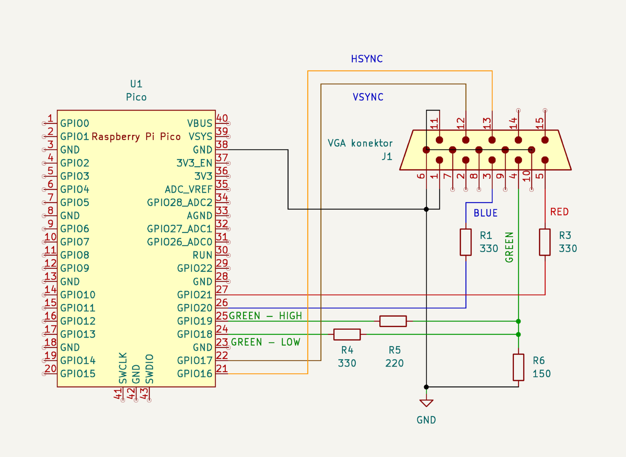
| Pokud uzemníme jenom jeden pin VGA konektoru, bude to fungovat, ale obraz bude nestabilní a ošklivý. Je lepší přizemnit všechny nepoužité piny na VGA konektoru. |

Celý program
/**
 * Hunter Adams (vha3@cornell.edu)
 *
 * HARDWARE CONNECTIONS
 *  - GPIO 16 ---> VGA Hsync
 *  - GPIO 17 ---> VGA Vsync
 *  - GPIO 18 ---> 330 ohm resistor ---> VGA Red
 *  - GPIO 19 ---> 330 ohm resistor ---> VGA Green
 *  - GPIO 20 ---> 330 ohm resistor ---> VGA Blue
 *  - RP2040 GND ---> VGA GND
 *
 * RESOURCES USED
 *  - PIO state machines 0, 1, and 2 on PIO instance 0
 *  - DMA channels 0, 1, 2, and 3
 *  - 153.6 kBytes of RAM (for pixel color data)
 *
 * Protothreads v1.1.1
 * Threads:
 * core 0:
 * Graphics demo
 * blink LED25
 * core 1:
 * Toggle gpio 4
 * Serial i/o
 */
// ==========================================
// === VGA graphics library
// ==========================================
#include "vga16_graphics.h"
#include <stdio.h>
#include <stdlib.h>
// #include <math.h>
#include "pico/stdlib.h"
#include "hardware/pio.h"
#include "hardware/dma.h"
// // Our assembled programs:
// // Each gets the name <pio_filename.pio.h>
// #include "hsync.pio.h"
// #include "vsync.pio.h"
// #include "rgb.pio.h"

// ==========================================
// === protothreads globals
// ==========================================
#include "hardware/sync.h"
#include "hardware/timer.h"
#include "pico/multicore.h"
#include "string.h"
// protothreads header
#include "pt_cornell_rp2040_v1_1_1.h"

// ==========================================

// Some globals for storing timer information
volatile unsigned int time_accum = 0;
unsigned int time_accum_old = 0 ;
char timetext[40];

// Timer interrupt
bool repeating_timer_callback(struct repeating_timer *t) {

    time_accum += 1 ;
    return true;
}

// ==================================================
// === graphics demo -- RUNNING on core 0
// ==================================================
static PT_THREAD (protothread_graphics(struct pt *pt)) {
    PT_BEGIN(pt);
    // the protothreads interval timer
    PT_INTERVAL_INIT() ;

    // circle radii
    static short circle_x = 0 ;

    // color chooser
    static char color_index = 0 ;

    // position of the disc primitive
    static short disc_x = 0 ;
    // position of the box primitive
    static short box_x = 0 ;
    // position of vertical line primitive
    static short Vline_x = 350;
    // position of horizontal line primitive
    static short Hline_y = 250;

    // Draw some filled rectangles
    fillRect(64, 0, 176, 50, BLUE); // blue box
    fillRect(250, 0, 176, 50, DARK_ORANGE); // red box
    fillRect(435, 0, 176, 50, GREEN); // green box

    // Write some text
    setTextColor(WHITE) ;
    setCursor(65, 0) ;
    setTextSize(1) ;
    writeString("Raspberry Pi Pico") ;
    setCursor(65, 10) ;
    writeString("Graphics primitives demo") ;
    setCursor(65, 20) ;
    writeString("Hunter Adams") ;
    setCursor(65, 30) ;
    writeString("vha3@cornell.edu") ;
    setCursor(445, 10) ;
    setTextColor(BLACK) ;
    setTextSize(1) ;
    writeString("Protothreads rp2040 v1.1.1") ;
    setTextColor(WHITE) ;

    // Setup a 1Hz timer
    static struct repeating_timer timer;
    add_repeating_timer_ms(-1000, repeating_timer_callback, NULL, &timer);

     char video_buffer[32];
    setTextColor2(WHITE, BLACK) ;
    setTextSize(1) ;
    for (int i=0; i<4; i++) {
      for (int j=0; j<4; j++){
        fillRect(i*70+20, 150+j*70, 60, 60, i+4*j);
        setCursor(i*70+20, 150+j*70) ;
        sprintf(video_buffer, "%2d", i+4*j);
        writeString(video_buffer) ;
      }
    }
    // first row of colors
    setCursor(0*70+20, 200+0*70) ;
    writeString("BLACK") ;
    setCursor(1*70+20, 200+0*70) ;
    writeString("DARK_GREEN") ;
    setCursor(2*70+20, 200+0*70) ;
    writeString("MED_GREEN") ;
    setCursor(3*70+20, 200+0*70) ;
    writeString("GREEN") ;
    // second row of colors
    setCursor(0*70+20, 200+1*70) ;
    writeString("DARK_BLUE") ;
    setCursor(1*70+20, 200+1*70) ;
    writeString("BLUE") ;
    setCursor(2*70+20, 200+1*70) ;
    writeString("LIGHT_BLUE") ;
    setCursor(3*70+20, 200+1*70) ;
    writeString("CYAN") ;
    // thrid row of colors
    setCursor(0*70+20, 200+2*70) ;
    writeString("RED") ;
    setCursor(1*70+20, 200+2*70) ;
    writeString("DARK_ORANGE") ;
    setCursor(2*70+20, 200+2*70) ;
    writeString("ORANGE") ;
    setCursor(3*70+20, 200+2*70) ;
    writeString("YELLOW") ;
    // fourth row of colors
    setCursor(0*70+20, 200+3*70) ;
    writeString("MAGENTA") ;
    setCursor(1*70+20, 200+3*70) ;
    writeString("PINK") ;
    setCursor(2*70+20, 200+3*70) ;
    writeString("LIGHT_PINK") ;
    setCursor(3*70+20, 200+3*70) ;
    writeString("WHITE") ;

    while(true) {

        // Modify the color chooser
        if (color_index ++ == 15) color_index = 0 ;

        // A row of filled circles
        fillCircle(disc_x, 100, 20, color_index);
        disc_x += 35 ;
        if (disc_x > 640) disc_x = 0;


        // A brief nap
        PT_YIELD_usec(100000) ;
   }
   PT_END(pt);
} // graphics thread

// ==================================================
// === toggle25 thread on core 0
// ==================================================
// the on-board LED blinks
static PT_THREAD (protothread_toggle25(struct pt *pt))
{
    PT_BEGIN(pt);
    static bool LED_state = false ;

     // set up LED p25 to blink
     gpio_init(25) ;
     gpio_set_dir(25, GPIO_OUT) ;
     gpio_put(25, true);
     // data structure for interval timer
     PT_INTERVAL_INIT() ;

      while(1) {
        // yield time 0.1 second
        //PT_YIELD_usec(100000) ;
        PT_YIELD_INTERVAL(100000) ;

        // toggle the LED on PICO
        LED_state = LED_state? false : true ;
        gpio_put(25, LED_state);
        //
        // NEVER exit while
      } // END WHILE(1)
  PT_END(pt);
} // blink thread


// ==================================================
// === toggle gpio 4 thread -- RUNNING on core 1
// ==================================================
// toggle gpio 4
static PT_THREAD (protothread_toggle_gpio4(struct pt *pt))
{
    PT_BEGIN(pt);
    static bool LED_state = false ;
    //
     // set up LED gpio 4 to blink
     gpio_init(4) ;
     gpio_set_dir(4, GPIO_OUT) ;
     gpio_put(4, true);
     // data structure for interval timer
     PT_INTERVAL_INIT() ;

      while(1) {
        //
        PT_YIELD_INTERVAL(20) ;
        // toggle gpio 4
        LED_state = !LED_state ;
        gpio_put(4, LED_state);
        //
        // NEVER exit while
      } // END WHILE(1)
  PT_END(pt);
} // blink thread

// ==================================================
// === user's serial input thread on core 1
// ==================================================
// serial_read an serial_write do not block any thread
// except this one
static PT_THREAD (protothread_serial(struct pt *pt))
{
    PT_BEGIN(pt);
      static int test_in1, test_in2, sum ;
      //
      while(1) {
        // print prompt
        sprintf(pt_serial_out_buffer, "input two numbers: ");
        // spawn a thread to do the non-blocking write
        serial_write ;

        // spawn a thread to do the non-blocking serial read
         serial_read ;
        // convert input string to number
        sscanf(pt_serial_in_buffer,"%d %d", &test_in1, &test_in2) ;

        // add and convert back to sring
        sprintf(pt_serial_out_buffer,"sum = %d\r\n", test_in1 + test_in2);
        // spawn a thread to do the non-blocking serial write
         serial_write ;

        // NEVER exit while
      } // END WHILE(1)
  PT_END(pt);
} // serial thread

// ========================================
// === core 1 main -- started in main below
// ========================================
void core1_main(){
  //
  //  === add threads  ====================
  // for core 1
  pt_add_thread(protothread_toggle_gpio4) ;
  pt_add_thread(protothread_serial) ;
  //
  // === initalize the scheduler ==========
  pt_schedule_start ;
  // NEVER exits
  // ======================================
}

// ========================================
// === core 0 main
// ========================================
int main(){
  // set the clock
  //set_sys_clock_khz(250000, true); // 171us
  // start the serial i/o
  stdio_init_all() ;
  // announce the threader version on system reset
  printf("\n\rProtothreads RP2040 v1.1 two-core\n\r");

  // Initialize the VGA screen
  initVGA() ;

  // start core 1 threads
  multicore_reset_core1();
  multicore_launch_core1(&core1_main);

  // === config threads ========================
  // for core 0
  pt_add_thread(protothread_graphics);
  pt_add_thread(protothread_toggle25);
  //
  // === initalize the scheduler ===============
  pt_schedule_start ;
  // NEVER exits
  // ===========================================
} // end main/**
* Hunter Adams (vha3@cornell.edu)
* modifed for 16 colors by BRL4
*
*
* HARDWARE CONNECTIONS
* - GPIO 16 ---> VGA Hsync
* - GPIO 17 ---> VGA Vsync
* - GPIO 18 ---> 660 ohm resistor ---> VGA Green
* - GPIO 19 ---> 470 ohm resistor ---> VGA Green
* - GPIO 20 ---> 330 ohm resistor ---> VGA Blue
* - GPIO 21 ---> 330 ohm resistor ---> VGA Red
* - RP2040 GND ---> VGA GND
*
* RESOURCES USED
* - PIO state machines 0, 1, and 2 on PIO instance 0
* - DMA channels 0, 1, 2, and 3
* - 153.6 kBytes of RAM (for pixel color data)
*
* NOTE
* - This is a translation of the display primitives
* for the PIC32 written by Bruce Land and students
*
*/
// Give the I/O pins that we're using some names that make sense - usable in main()
enum vga_pins {HSYNC=16, VSYNC, LO_GRN, HI_GRN, BLUE_PIN, RED_PIN} ;
// We can only produce 8 (3-bit) colors, so let's give them readable names - usable in main()
//enum colors {BLACK, RED, GREEN, YELLOW, BLUE, MAGENTA, CYAN, WHITE} ;
enum colors {BLACK, DARK_GREEN, MED_GREEN, GREEN,
DARK_BLUE, BLUE, LIGHT_BLUE, CYAN,
RED, DARK_ORANGE, ORANGE, YELLOW,
MAGENTA, PINK, LIGHT_PINK, WHITE} ;
// VGA primitives - usable in main
void initVGA(void) ;
void drawPixel(short x, short y, char color) ;
void drawVLine(short x, short y, short h, char color) ;
void drawHLine(short x, short y, short w, char color) ;
void drawLine(short x0, short y0, short x1, short y1, char color) ;
void drawRect(short x, short y, short w, short h, char color);
void drawCircle(short x0, short y0, short r, char color) ;
void drawCircleHelper( short x0, short y0, short r, unsigned char cornername, char color) ;
void fillCircle(short x0, short y0, short r, char color) ;
void fillCircleHelper(short x0, short y0, short r, unsigned char cornername, short delta, char color) ;
void drawRoundRect(short x, short y, short w, short h, short r, char color) ;
void fillRoundRect(short x, short y, short w, short h, short r, char color) ;
void fillRect(short x, short y, short w, short h, char color) ;
void drawChar(short x, short y, unsigned char c, char color, char bg, unsigned char size) ;
void setCursor(short x, short y);
void setTextColor(char c);
void setTextColor2(char c, char bg);
void setTextSize(unsigned char s);
void setTextWrap(char w);
void tft_write(unsigned char c) ;
void writeString(char* str) ;#include <stdio.h>
#include <stdlib.h>
#include "pico/stdlib.h"
#include "hardware/pio.h"
#include "hardware/dma.h"
// Our assembled programs:
// Each gets the name <pio_filename.pio.h>
#include "hsync.pio.h"
#include "vsync.pio.h"
#include "rgb.pio.h"
// Header file
#include "vga16_graphics.h"
// Font file
#include "glcdfont.c"
// VGA timing constants
#define H_ACTIVE 655 // (active + frontporch - 1) - one cycle delay for mov
#define V_ACTIVE 479 // (active - 1)
#define RGB_ACTIVE 319 // (horizontal active)/2 - 1
// #define RGB_ACTIVE 639 // change to this if 1 pixel/byte
// Length of the pixel array, and number of DMA transfers
#define TXCOUNT 153600 // Total pixels/2 (since we have 2 pixels per byte)
// Pixel color array that is DMA's to the PIO machines and
// a pointer to the ADDRESS of this color array.
// Note that this array is automatically initialized to all 0's (black)
unsigned char vga_data_array[TXCOUNT];
char * address_pointer = &vga_data_array[0] ;
// Bit masks for drawPixel routine
#define TOPMASK 0b00001111
#define BOTTOMMASK 0b11110000
// For drawLine
#define swap(a, b) { short t = a; a = b; b = t; }
// For writing text
#define tabspace 4 // number of spaces for a tab
// For accessing the font library
#define pgm_read_byte(addr) (*(const unsigned char *)(addr))
// For drawing characters
unsigned short cursor_y, cursor_x, textsize ;
char textcolor, textbgcolor, wrap;
// Screen width/height
#define _width 640
#define _height 480
void initVGA() {
// Choose which PIO instance to use (there are two instances, each with 4 state machines)
PIO pio = pio0;
// Our assembled program needs to be loaded into this PIO's instruction
// memory. This SDK function will find a location (offset) in the
// instruction memory where there is enough space for our program. We need
// to remember these locations!
//
// We only have 32 instructions to spend! If the PIO programs contain more than
// 32 instructions, then an error message will get thrown at these lines of code.
//
// The program name comes from the .program part of the pio file
// and is of the form <program name_program>
uint hsync_offset = pio_add_program(pio, &hsync_program);
uint vsync_offset = pio_add_program(pio, &vsync_program);
uint rgb_offset = pio_add_program(pio, &rgb_program);
// Manually select a few state machines from pio instance pio0.
uint hsync_sm = 0;
uint vsync_sm = 1;
uint rgb_sm = 2;
// Call the initialization functions that are defined within each PIO file.
// Why not create these programs here? By putting the initialization function in
// the pio file, then all information about how to use/setup that state machine
// is consolidated in one place. Here in the C, we then just import and use it.
hsync_program_init(pio, hsync_sm, hsync_offset, HSYNC);
vsync_program_init(pio, vsync_sm, vsync_offset, VSYNC);
rgb_program_init(pio, rgb_sm, rgb_offset, LO_GRN);
/////////////////////////////////////////////////////////////////////////////////////////////////////
// ============================== PIO DMA Channels =================================================
/////////////////////////////////////////////////////////////////////////////////////////////////////
// DMA channels - 0 sends color data, 1 reconfigures and restarts 0
int rgb_chan_0 = 0;
int rgb_chan_1 = 1;
// Channel Zero (sends color data to PIO VGA machine)
dma_channel_config c0 = dma_channel_get_default_config(rgb_chan_0); // default configs
channel_config_set_transfer_data_size(&c0, DMA_SIZE_8); // 8-bit txfers
channel_config_set_read_increment(&c0, true); // yes read incrementing
channel_config_set_write_increment(&c0, false); // no write incrementing
channel_config_set_dreq(&c0, DREQ_PIO0_TX2) ; // DREQ_PIO0_TX2 pacing (FIFO)
channel_config_set_chain_to(&c0, rgb_chan_1); // chain to other channel
dma_channel_configure(
rgb_chan_0, // Channel to be configured
&c0, // The configuration we just created
&pio->txf[rgb_sm], // write address (RGB PIO TX FIFO)
&vga_data_array, // The initial read address (pixel color array)
TXCOUNT, // Number of transfers; in this case each is 1 byte.
false // Don't start immediately.
);
// Channel One (reconfigures the first channel)
dma_channel_config c1 = dma_channel_get_default_config(rgb_chan_1); // default configs
channel_config_set_transfer_data_size(&c1, DMA_SIZE_32); // 32-bit txfers
channel_config_set_read_increment(&c1, false); // no read incrementing
channel_config_set_write_increment(&c1, false); // no write incrementing
channel_config_set_chain_to(&c1, rgb_chan_0); // chain to other channel
dma_channel_configure(
rgb_chan_1, // Channel to be configured
&c1, // The configuration we just created
&dma_hw->ch[rgb_chan_0].read_addr, // Write address (channel 0 read address)
&address_pointer, // Read address (POINTER TO AN ADDRESS)
1, // Number of transfers, in this case each is 4 byte
false // Don't start immediately.
);
/////////////////////////////////////////////////////////////////////////////////////////////////////
/////////////////////////////////////////////////////////////////////////////////////////////////////
// Initialize PIO state machine counters. This passes the information to the state machines
// that they retrieve in the first 'pull' instructions, before the .wrap_target directive
// in the assembly. Each uses these values to initialize some counting registers.
pio_sm_put_blocking(pio, hsync_sm, H_ACTIVE);
pio_sm_put_blocking(pio, vsync_sm, V_ACTIVE);
pio_sm_put_blocking(pio, rgb_sm, RGB_ACTIVE);
// Start the two pio machine IN SYNC
// Note that the RGB state machine is running at full speed,
// so synchronization doesn't matter for that one. But, we'll
// start them all simultaneously anyway.
pio_enable_sm_mask_in_sync(pio, ((1u << hsync_sm) | (1u << vsync_sm) | (1u << rgb_sm)));
// Start DMA channel 0. Once started, the contents of the pixel color array
// will be continously DMA's to the PIO machines that are driving the screen.
// To change the contents of the screen, we need only change the contents
// of that array.
dma_start_channel_mask((1u << rgb_chan_0)) ;
}
// A function for drawing a pixel with a specified color.
// Note that because information is passed to the PIO state machines through
// a DMA channel, we only need to modify the contents of the array and the
// pixels will be automatically updated on the screen.
void drawPixel(short x, short y, char color) {
// Range checks (640x480 display)
if (x > 639) x = 639 ;
if (x < 0) x = 0 ;
if (y < 0) y = 0 ;
if (y > 479) y = 479 ;
//if((x > 639) | (x < 0) | (y > 479) | (y < 0) ) return;
// Which pixel is it?
int pixel = ((640 * y) + x) ;
// Is this pixel stored in the first 4 bits
// of the vga data array index, or the second
// 4 bits? Check, then mask.
if (pixel & 1) {
vga_data_array[pixel>>1] = (vga_data_array[pixel>>1] & TOPMASK) | (color << 4) ;
}
else {
vga_data_array[pixel>>1] = (vga_data_array[pixel>>1] & BOTTOMMASK) | (color) ;
}
}
void drawVLine(short x, short y, short h, char color) {
for (short i=y; i<(y+h); i++) {
drawPixel(x, i, color) ;
}
}
void drawHLine(short x, short y, short w, char color) {
for (short i=x; i<(x+w); i++) {
drawPixel(i, y, color) ;
}
}
// Bresenham's algorithm - thx wikipedia and thx Bruce!
void drawLine(short x0, short y0, short x1, short y1, char color) {
/* Draw a straight line from (x0,y0) to (x1,y1) with given color
* Parameters:
* x0: x-coordinate of starting point of line. The x-coordinate of
* the top-left of the screen is 0. It increases to the right.
* y0: y-coordinate of starting point of line. The y-coordinate of
* the top-left of the screen is 0. It increases to the bottom.
* x1: x-coordinate of ending point of line. The x-coordinate of
* the top-left of the screen is 0. It increases to the right.
* y1: y-coordinate of ending point of line. The y-coordinate of
* the top-left of the screen is 0. It increases to the bottom.
* color: 3-bit color value for line
*/
short steep = abs(y1 - y0) > abs(x1 - x0);
if (steep) {
swap(x0, y0);
swap(x1, y1);
}
if (x0 > x1) {
swap(x0, x1);
swap(y0, y1);
}
short dx, dy;
dx = x1 - x0;
dy = abs(y1 - y0);
short err = dx / 2;
short ystep;
if (y0 < y1) {
ystep = 1;
} else {
ystep = -1;
}
for (; x0<=x1; x0++) {
if (steep) {
drawPixel(y0, x0, color);
} else {
drawPixel(x0, y0, color);
}
err -= dy;
if (err < 0) {
y0 += ystep;
err += dx;
}
}
}
// Draw a rectangle
void drawRect(short x, short y, short w, short h, char color) {
/* Draw a rectangle outline with top left vertex (x,y), width w
* and height h at given color
* Parameters:
* x: x-coordinate of top-left vertex. The x-coordinate of
* the top-left of the screen is 0. It increases to the right.
* y: y-coordinate of top-left vertex. The y-coordinate of
* the top-left of the screen is 0. It increases to the bottom.
* w: width of the rectangle
* h: height of the rectangle
* color: 16-bit color of the rectangle outline
* Returns: Nothing
*/
drawHLine(x, y, w, color);
drawHLine(x, y+h-1, w, color);
drawVLine(x, y, h, color);
drawVLine(x+w-1, y, h, color);
}
void drawCircle(short x0, short y0, short r, char color) {
/* Draw a circle outline with center (x0,y0) and radius r, with given color
* Parameters:
* x0: x-coordinate of center of circle. The top-left of the screen
* has x-coordinate 0 and increases to the right
* y0: y-coordinate of center of circle. The top-left of the screen
* has y-coordinate 0 and increases to the bottom
* r: radius of circle
* color: 16-bit color value for the circle. Note that the circle
* isn't filled. So, this is the color of the outline of the circle
* Returns: Nothing
*/
short f = 1 - r;
short ddF_x = 1;
short ddF_y = -2 * r;
short x = 0;
short y = r;
drawPixel(x0 , y0+r, color);
drawPixel(x0 , y0-r, color);
drawPixel(x0+r, y0 , color);
drawPixel(x0-r, y0 , color);
while (x<y) {
if (f >= 0) {
y--;
ddF_y += 2;
f += ddF_y;
}
x++;
ddF_x += 2;
f += ddF_x;
drawPixel(x0 + x, y0 + y, color);
drawPixel(x0 - x, y0 + y, color);
drawPixel(x0 + x, y0 - y, color);
drawPixel(x0 - x, y0 - y, color);
drawPixel(x0 + y, y0 + x, color);
drawPixel(x0 - y, y0 + x, color);
drawPixel(x0 + y, y0 - x, color);
drawPixel(x0 - y, y0 - x, color);
}
}
void drawCircleHelper( short x0, short y0, short r, unsigned char cornername, char color) {
// Helper function for drawing circles and circular objects
short f = 1 - r;
short ddF_x = 1;
short ddF_y = -2 * r;
short x = 0;
short y = r;
while (x<y) {
if (f >= 0) {
y--;
ddF_y += 2;
f += ddF_y;
}
x++;
ddF_x += 2;
f += ddF_x;
if (cornername & 0x4) {
drawPixel(x0 + x, y0 + y, color);
drawPixel(x0 + y, y0 + x, color);
}
if (cornername & 0x2) {
drawPixel(x0 + x, y0 - y, color);
drawPixel(x0 + y, y0 - x, color);
}
if (cornername & 0x8) {
drawPixel(x0 - y, y0 + x, color);
drawPixel(x0 - x, y0 + y, color);
}
if (cornername & 0x1) {
drawPixel(x0 - y, y0 - x, color);
drawPixel(x0 - x, y0 - y, color);
}
}
}
void fillCircle(short x0, short y0, short r, char color) {
/* Draw a filled circle with center (x0,y0) and radius r, with given color
* Parameters:
* x0: x-coordinate of center of circle. The top-left of the screen
* has x-coordinate 0 and increases to the right
* y0: y-coordinate of center of circle. The top-left of the screen
* has y-coordinate 0 and increases to the bottom
* r: radius of circle
* color: 16-bit color value for the circle
* Returns: Nothing
*/
drawVLine(x0, y0-r, 2*r+1, color);
fillCircleHelper(x0, y0, r, 3, 0, color);
}
void fillCircleHelper(short x0, short y0, short r, unsigned char cornername, short delta, char color) {
// Helper function for drawing filled circles
short f = 1 - r;
short ddF_x = 1;
short ddF_y = -2 * r;
short x = 0;
short y = r;
while (x<y) {
if (f >= 0) {
y--;
ddF_y += 2;
f += ddF_y;
}
x++;
ddF_x += 2;
f += ddF_x;
if (cornername & 0x1) {
drawVLine(x0+x, y0-y, 2*y+1+delta, color);
drawVLine(x0+y, y0-x, 2*x+1+delta, color);
}
if (cornername & 0x2) {
drawVLine(x0-x, y0-y, 2*y+1+delta, color);
drawVLine(x0-y, y0-x, 2*x+1+delta, color);
}
}
}
// Draw a rounded rectangle
void drawRoundRect(short x, short y, short w, short h, short r, char color) {
/* Draw a rounded rectangle outline with top left vertex (x,y), width w,
* height h and radius of curvature r at given color
* Parameters:
* x: x-coordinate of top-left vertex. The x-coordinate of
* the top-left of the screen is 0. It increases to the right.
* y: y-coordinate of top-left vertex. The y-coordinate of
* the top-left of the screen is 0. It increases to the bottom.
* w: width of the rectangle
* h: height of the rectangle
* color: 16-bit color of the rectangle outline
* Returns: Nothing
*/
// smarter version
drawHLine(x+r , y , w-2*r, color); // Top
drawHLine(x+r , y+h-1, w-2*r, color); // Bottom
drawVLine(x , y+r , h-2*r, color); // Left
drawVLine(x+w-1, y+r , h-2*r, color); // Right
// draw four corners
drawCircleHelper(x+r , y+r , r, 1, color);
drawCircleHelper(x+w-r-1, y+r , r, 2, color);
drawCircleHelper(x+w-r-1, y+h-r-1, r, 4, color);
drawCircleHelper(x+r , y+h-r-1, r, 8, color);
}
// Fill a rounded rectangle
void fillRoundRect(short x, short y, short w, short h, short r, char color) {
// smarter version
fillRect(x+r, y, w-2*r, h, color);
// draw four corners
fillCircleHelper(x+w-r-1, y+r, r, 1, h-2*r-1, color);
fillCircleHelper(x+r , y+r, r, 2, h-2*r-1, color);
}
// fill a rectangle
void fillRect(short x, short y, short w, short h, char color) {
/* Draw a filled rectangle with starting top-left vertex (x,y),
* width w and height h with given color
* Parameters:
* x: x-coordinate of top-left vertex; top left of screen is x=0
* and x increases to the right
* y: y-coordinate of top-left vertex; top left of screen is y=0
* and y increases to the bottom
* w: width of rectangle
* h: height of rectangle
* color: 3-bit color value
* Returns: Nothing
*/
// rudimentary clipping (drawChar w/big text requires this)
// if((x >= _width) || (y >= _height)) return;
// if((x + w - 1) >= _width) w = _width - x;
// if((y + h - 1) >= _height) h = _height - y;
// tft_setAddrWindow(x, y, x+w-1, y+h-1);
for(int i=x; i<(x+w); i++) {
for(int j=y; j<(y+h); j++) {
drawPixel(i, j, color);
}
}
}
// Draw a character
void drawChar(short x, short y, unsigned char c, char color, char bg, unsigned char size) {
char i, j;
if((x >= _width) || // Clip right
(y >= _height) || // Clip bottom
((x + 6 * size - 1) < 0) || // Clip left
((y + 8 * size - 1) < 0)) // Clip top
return;
for (i=0; i<6; i++ ) {
unsigned char line;
if (i == 5)
line = 0x0;
else
line = pgm_read_byte(font+(c*5)+i);
for ( j = 0; j<8; j++) {
if (line & 0x1) {
if (size == 1) // default size
drawPixel(x+i, y+j, color);
else { // big size
fillRect(x+(i*size), y+(j*size), size, size, color);
}
} else if (bg != color) {
if (size == 1) // default size
drawPixel(x+i, y+j, bg);
else { // big size
fillRect(x+i*size, y+j*size, size, size, bg);
}
}
line >>= 1;
}
}
}
inline void setCursor(short x, short y) {
/* Set cursor for text to be printed
* Parameters:
* x = x-coordinate of top-left of text starting
* y = y-coordinate of top-left of text starting
* Returns: Nothing
*/
cursor_x = x;
cursor_y = y;
}
inline void setTextSize(unsigned char s) {
/*Set size of text to be displayed
* Parameters:
* s = text size (1 being smallest)
* Returns: nothing
*/
textsize = (s > 0) ? s : 1;
}
inline void setTextColor(char c) {
// For 'transparent' background, we'll set the bg
// to the same as fg instead of using a flag
textcolor = textbgcolor = c;
}
inline void setTextColor2(char c, char b) {
/* Set color of text to be displayed
* Parameters:
* c = 16-bit color of text
* b = 16-bit color of text background
*/
textcolor = c;
textbgcolor = b;
}
inline void setTextWrap(char w) {
wrap = w;
}
void tft_write(unsigned char c){
if (c == '\n') {
cursor_y += textsize*8;
cursor_x = 0;
} else if (c == '\r') {
// skip em
} else if (c == '\t'){
int new_x = cursor_x + tabspace;
if (new_x < _width){
cursor_x = new_x;
}
} else {
drawChar(cursor_x, cursor_y, c, textcolor, textbgcolor, textsize);
cursor_x += textsize*6;
if (wrap && (cursor_x > (_width - textsize*6))) {
cursor_y += textsize*8;
cursor_x = 0;
}
}
}
inline void writeString(char* str){
/* Print text onto screen
* Call tft_setCursor(), tft_setTextColor(), tft_setTextSize()
* as necessary before printing
*/
while (*str){
tft_write(*str++);
}
}# cmake version
cmake_minimum_required(VERSION 3.13)
# include the sdk.cmake file
include(pico_sdk_import.cmake)
# give the project a name (anything you want)
project(vga16-graphics-project)
# initialize the sdk
pico_sdk_init()
#######
# name anything you want
add_executable(graphics_test)
# must match with pio filename and executable name from above
pico_generate_pio_header(graphics_test ${CMAKE_CURRENT_LIST_DIR}/hsync.pio)
pico_generate_pio_header(graphics_test ${CMAKE_CURRENT_LIST_DIR}/vsync.pio)
pico_generate_pio_header(graphics_test ${CMAKE_CURRENT_LIST_DIR}/rgb.pio)
# must match with executable name and source file names
target_sources(graphics_test PRIVATE
vga16_graphics_demo.c
vga16_graphics.c)
# must match with executable name
target_link_libraries(graphics_test PRIVATE
pico_stdlib
pico_bootsel_via_double_reset
hardware_pio
hardware_dma
hardware_adc
hardware_sync
hardware_irq
pico_multicore)
# must match with executable name
pico_add_extra_outputs(graphics_test)
add_compile_options(-Ofast)mkdir build
cd build
cmake ..
make -j8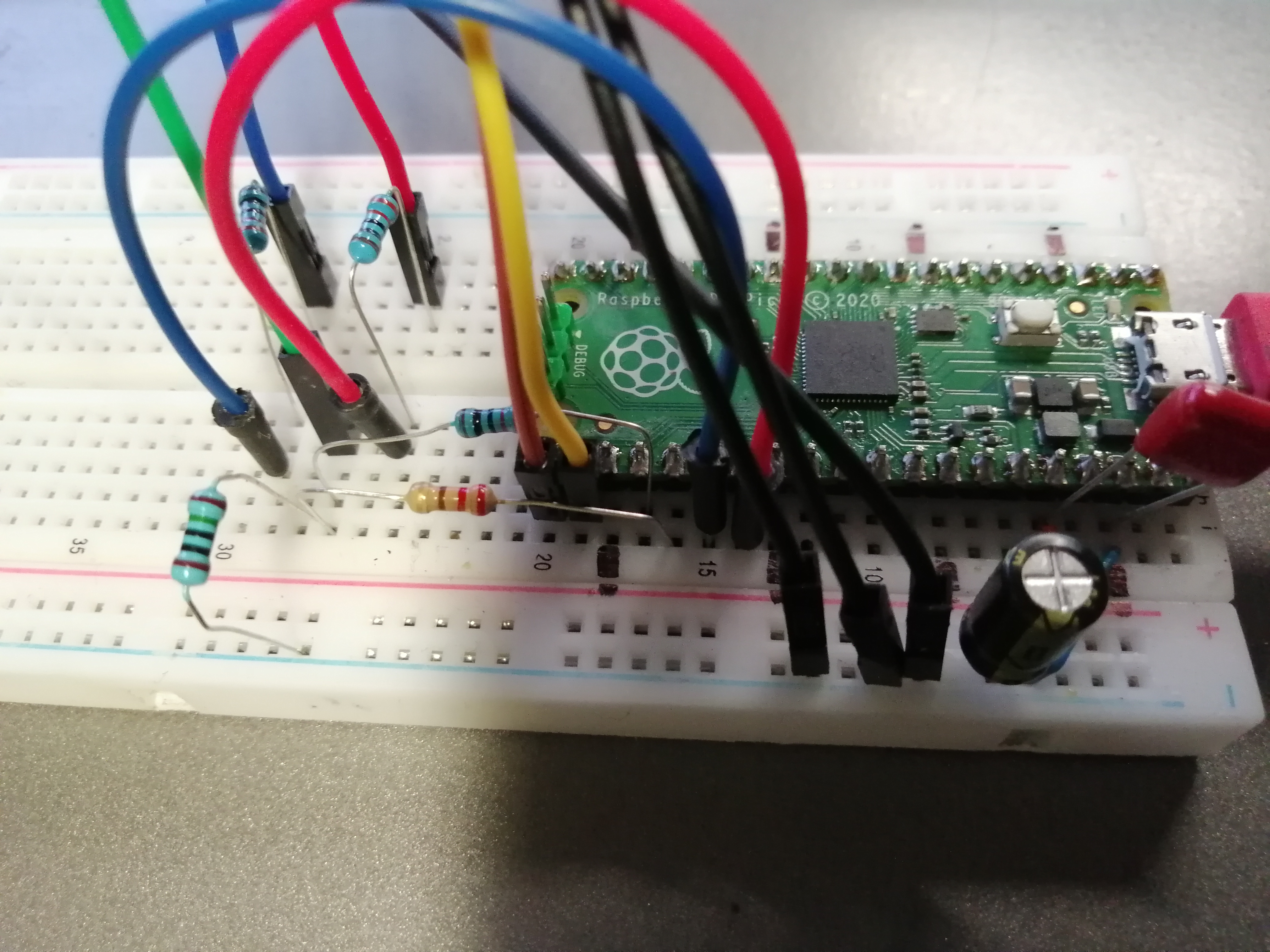
Závady
-
Stavové automaty Hsync a Vsync PIO by měly být spuštěny současně. Protože stavový automat RGB běží plnou rychlostí, synchronizace s ostatními dvěma není nutná.
-
Spouštěč pro čtení adresy DMA vyžaduje ukazatel na adresu začátku barevného pole, nikoli samotnou adresu (odhalení této chyby chvíli trvalo).
-
Při pokusu o čtení vysokorychlostních signálů na osciloskopu si všimněte, že v přívodu klipu je určitá kapacita a v zemnícím krokosvorce určitá indukčnost. Tato kapacita/indukčnost může způsobit určité zvonění. Chcete-li toto zvonění zmírnit, odstraňte přívod klipu a zemnící kabel, znovu nalaďte sondu v této konfiguraci a uzemněte vodič pomocí krátkého drátu. Tím se zvonění výrazně sníží.
-
Registr
read_addrpro kanál DMA 0 očekává ukazatel na adresu začátku pixelového pole, nikoli samotnou adresu. -
Při napájení z USB počítače je obraz velmi mizerný, při napájení z jiného zdroje je stabilní a pěkný. Bylo to způsobeno tím, že jsem měl uzemněn jenom jeden pin na VGA konktoru. Přizemněním dalších nepoužitých pinů VGA konektoru problém zmizel.