Fungující rádio 2.4GHz.
Konstrukce
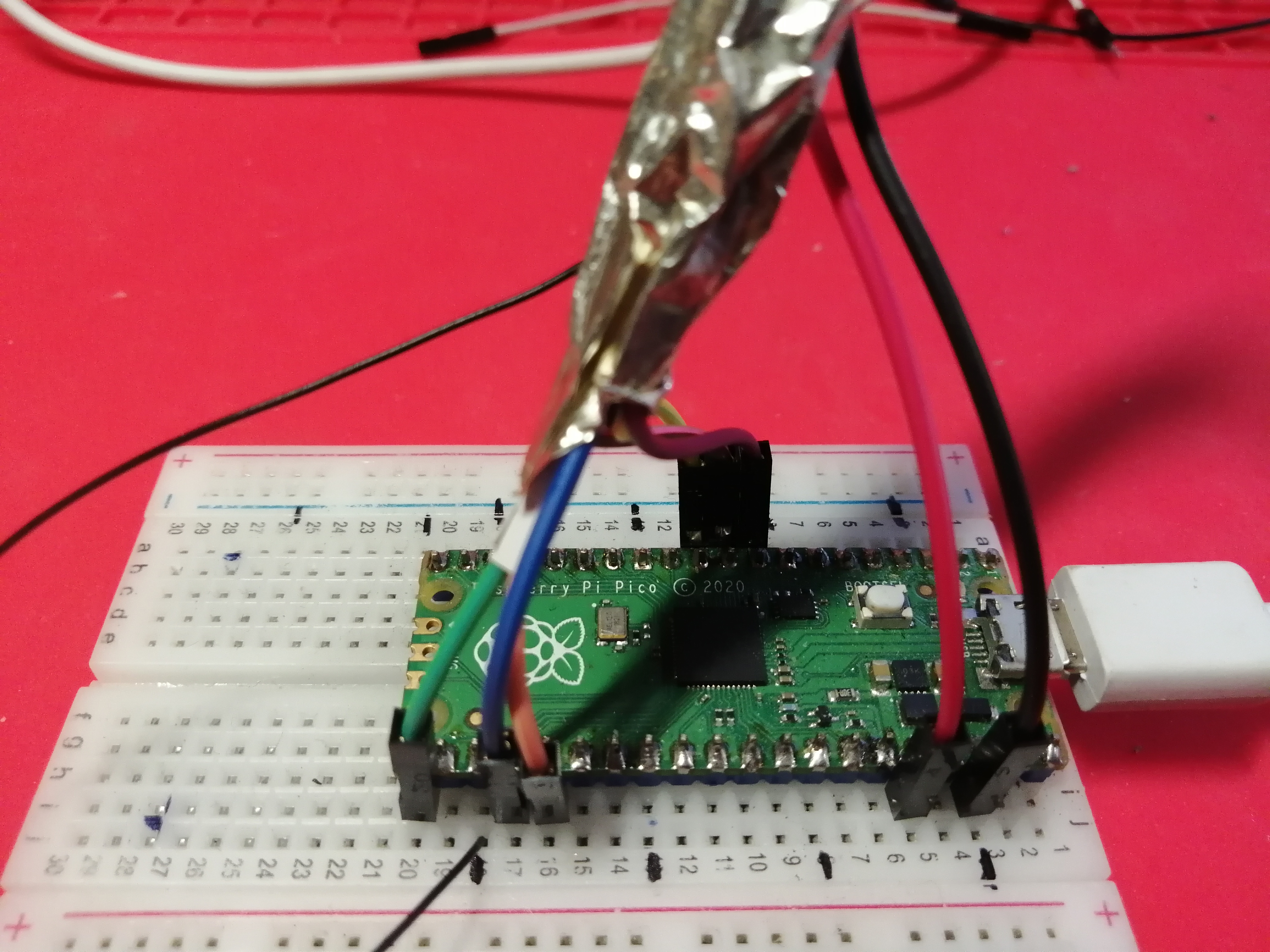
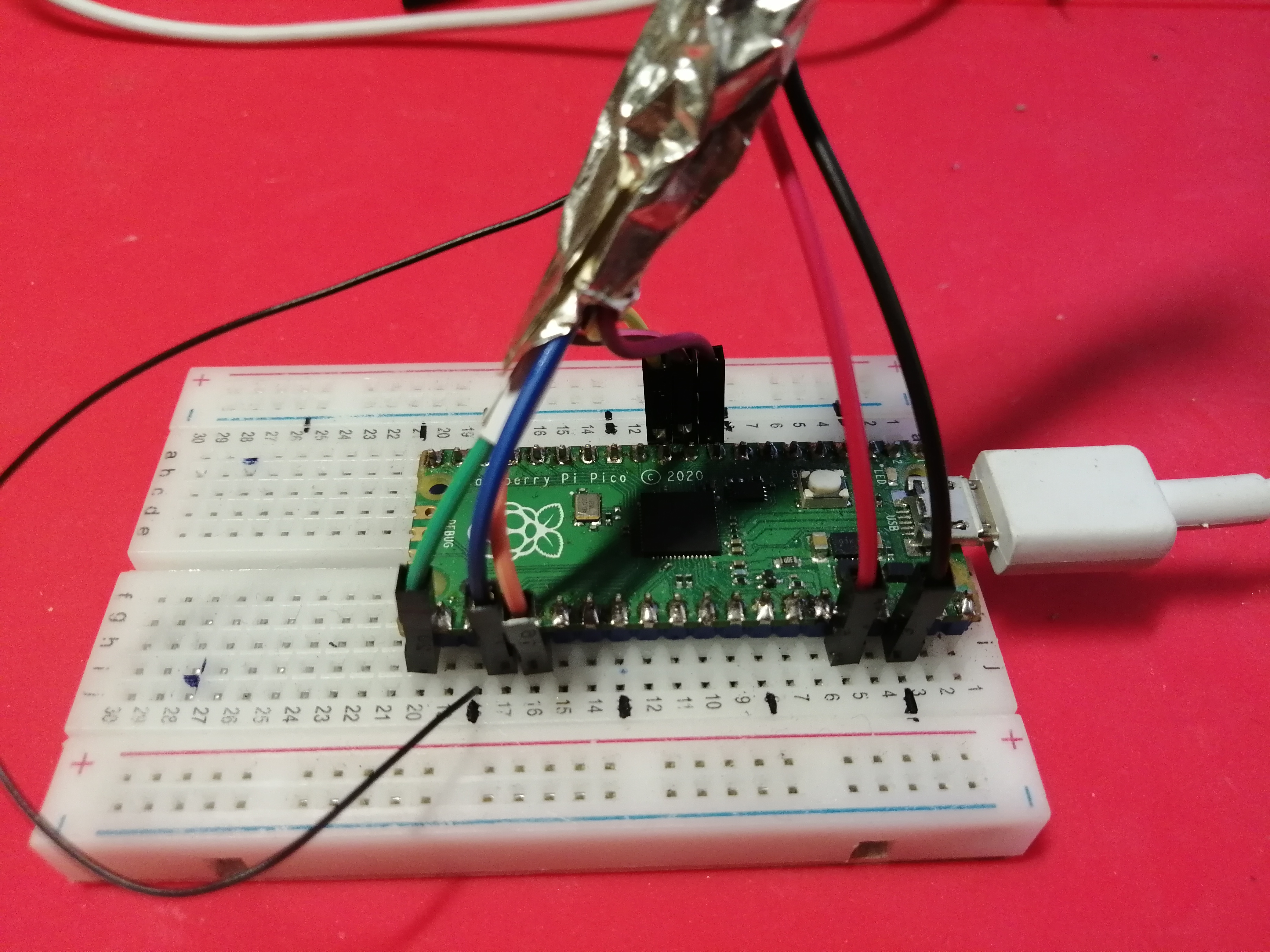
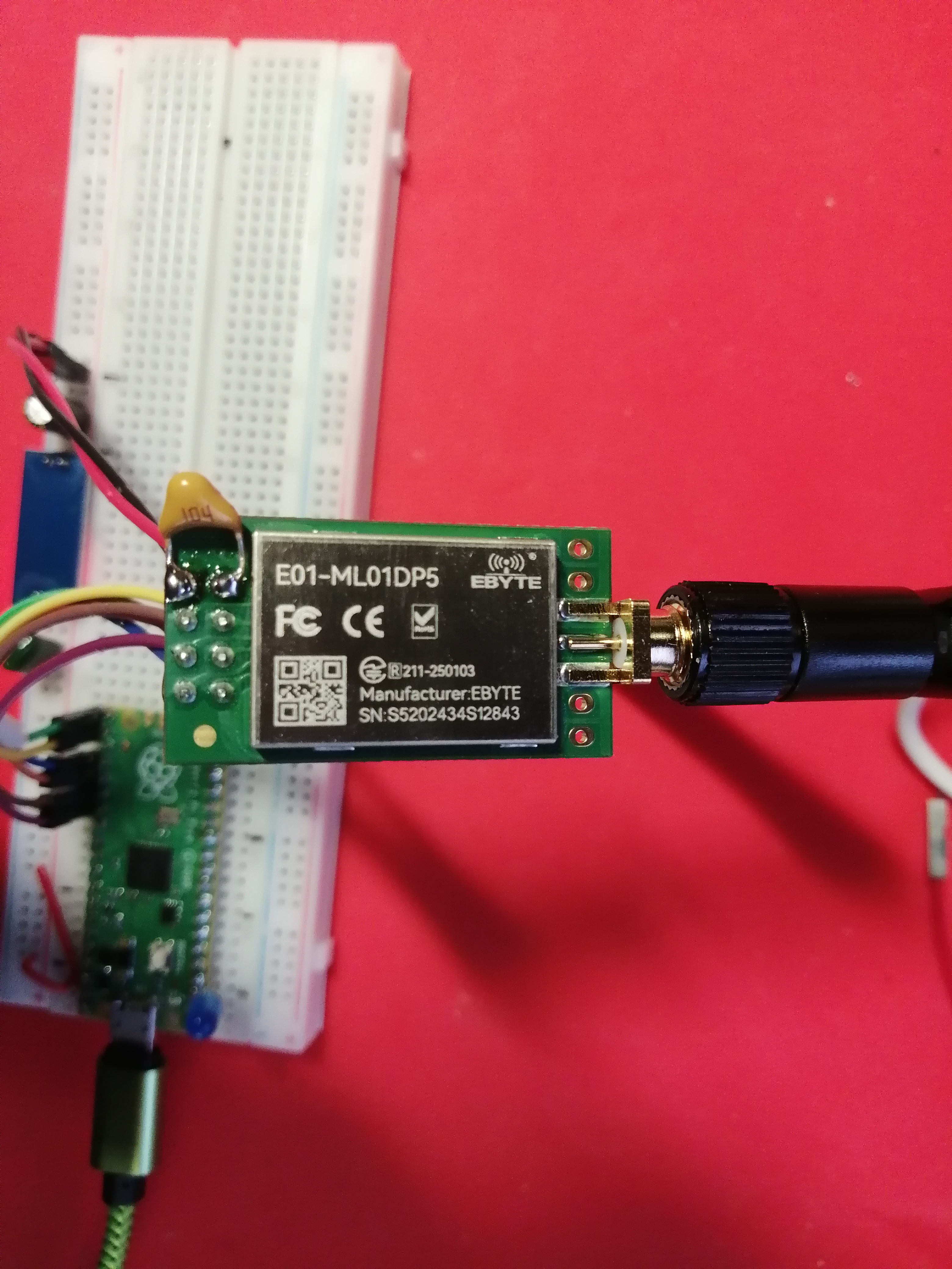

Přijímač
Přijímač
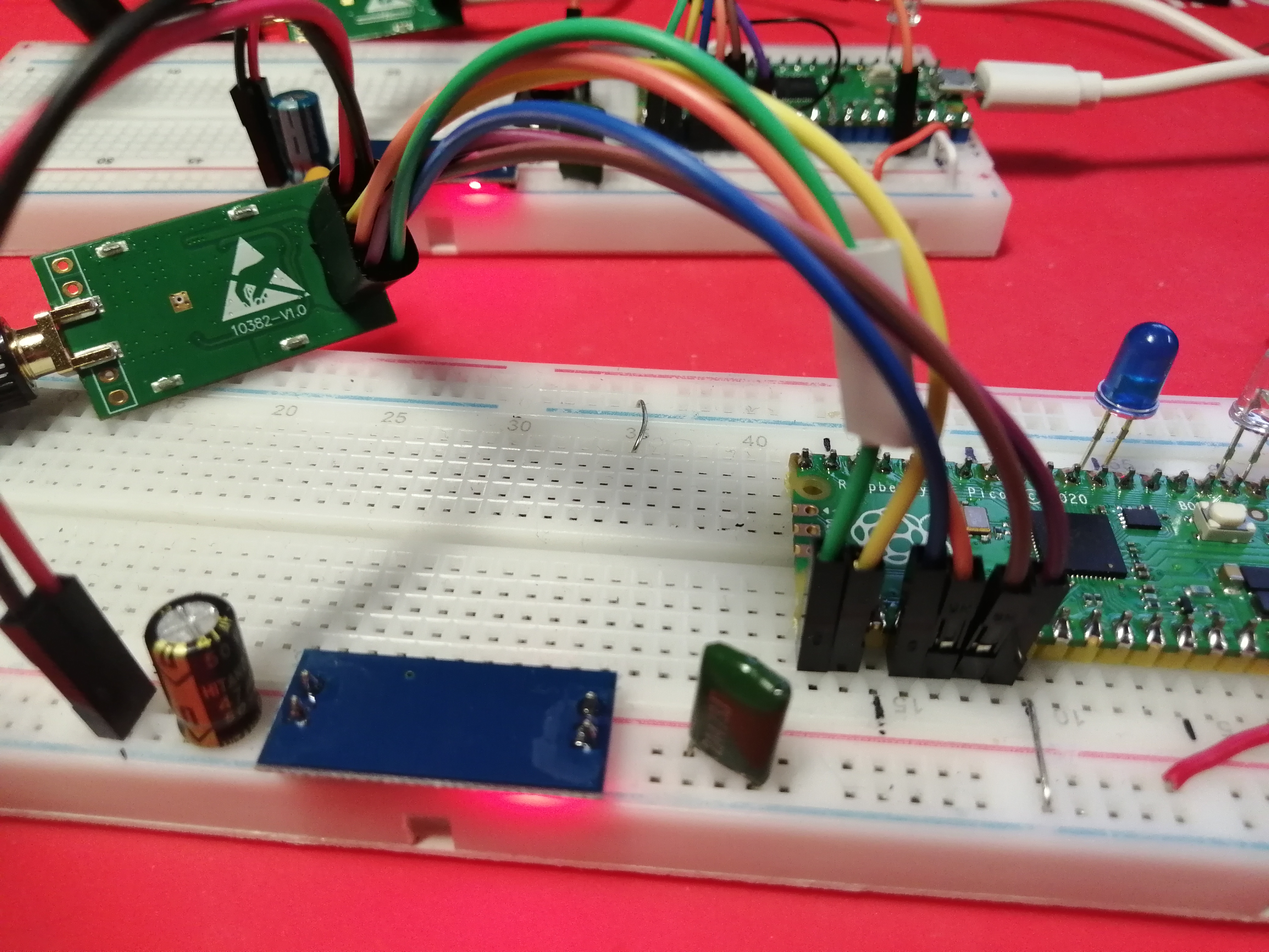
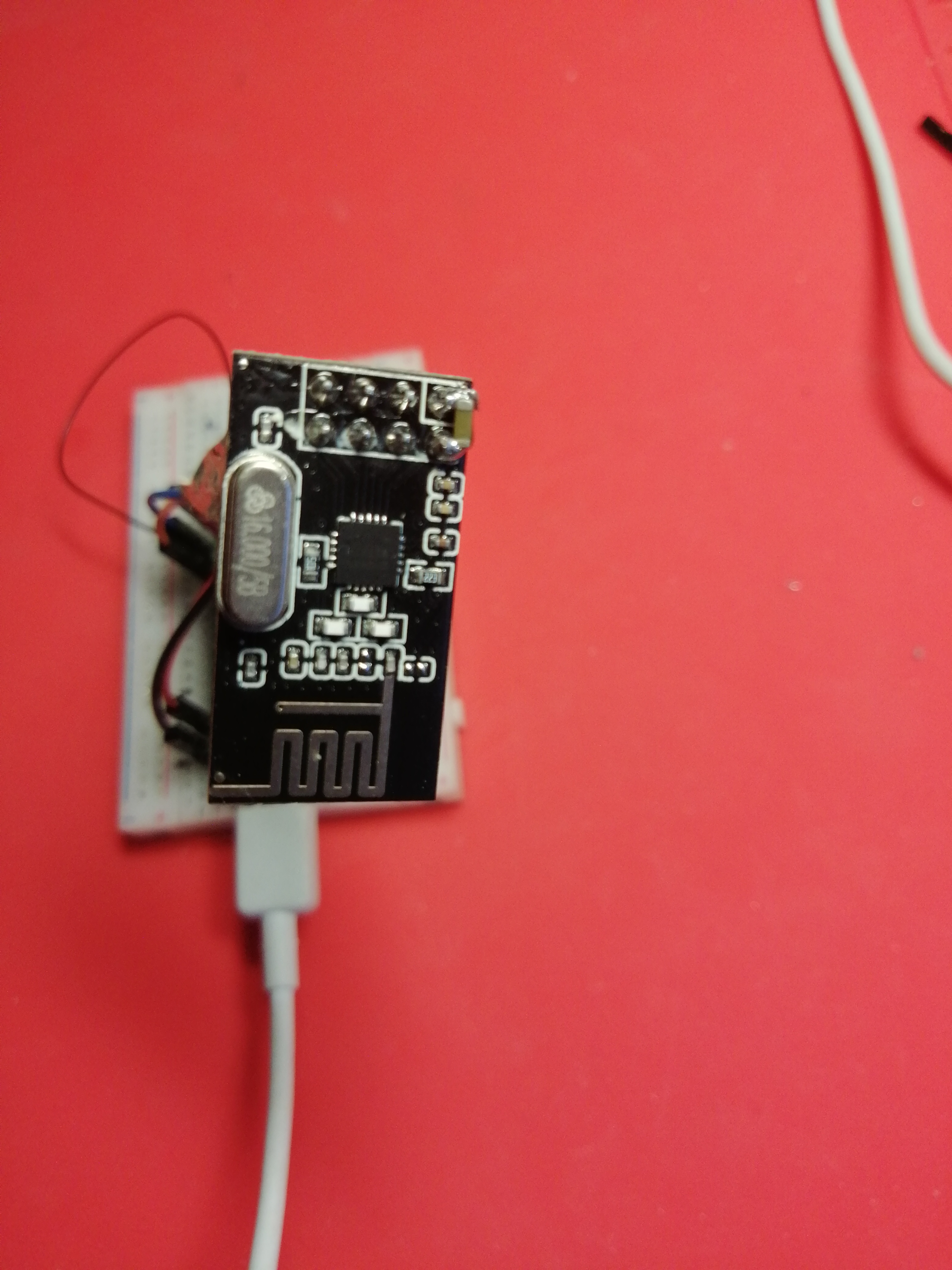
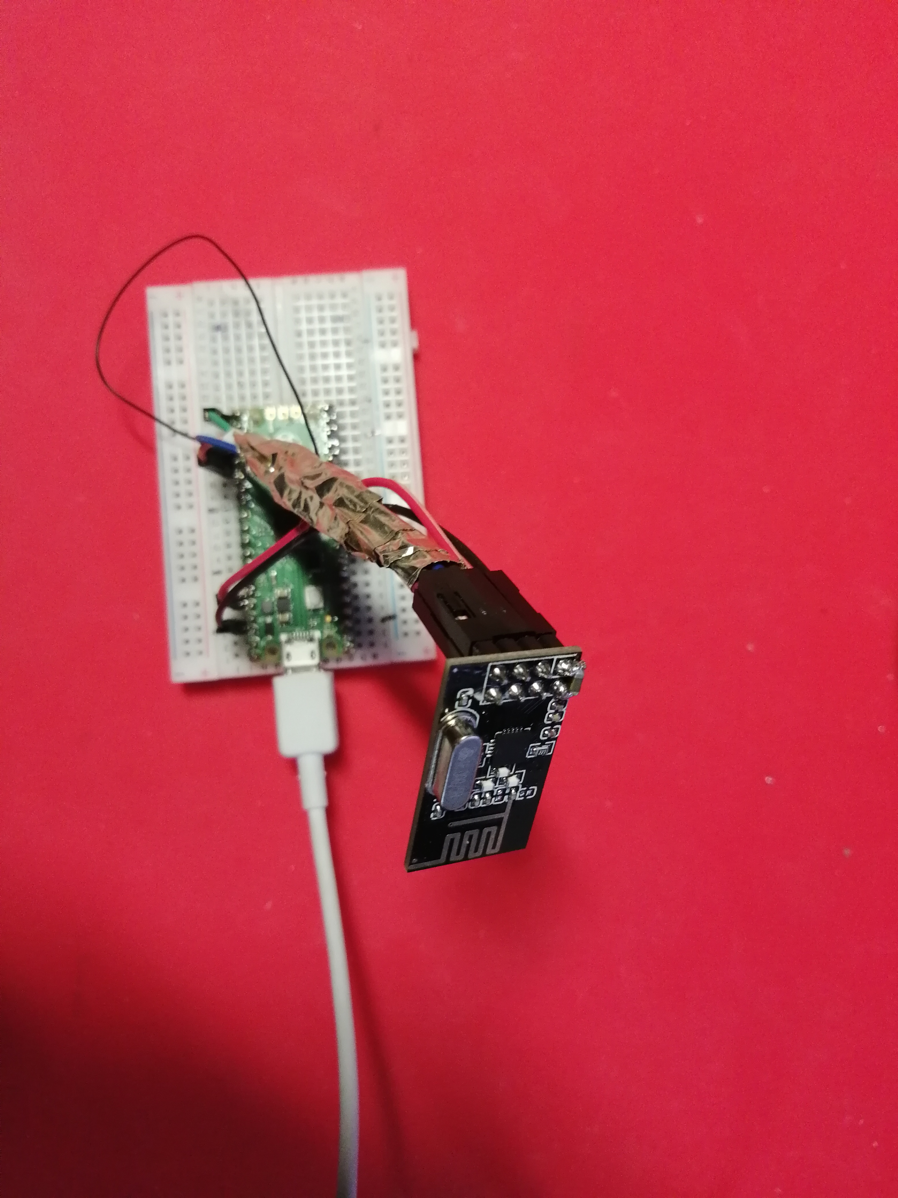
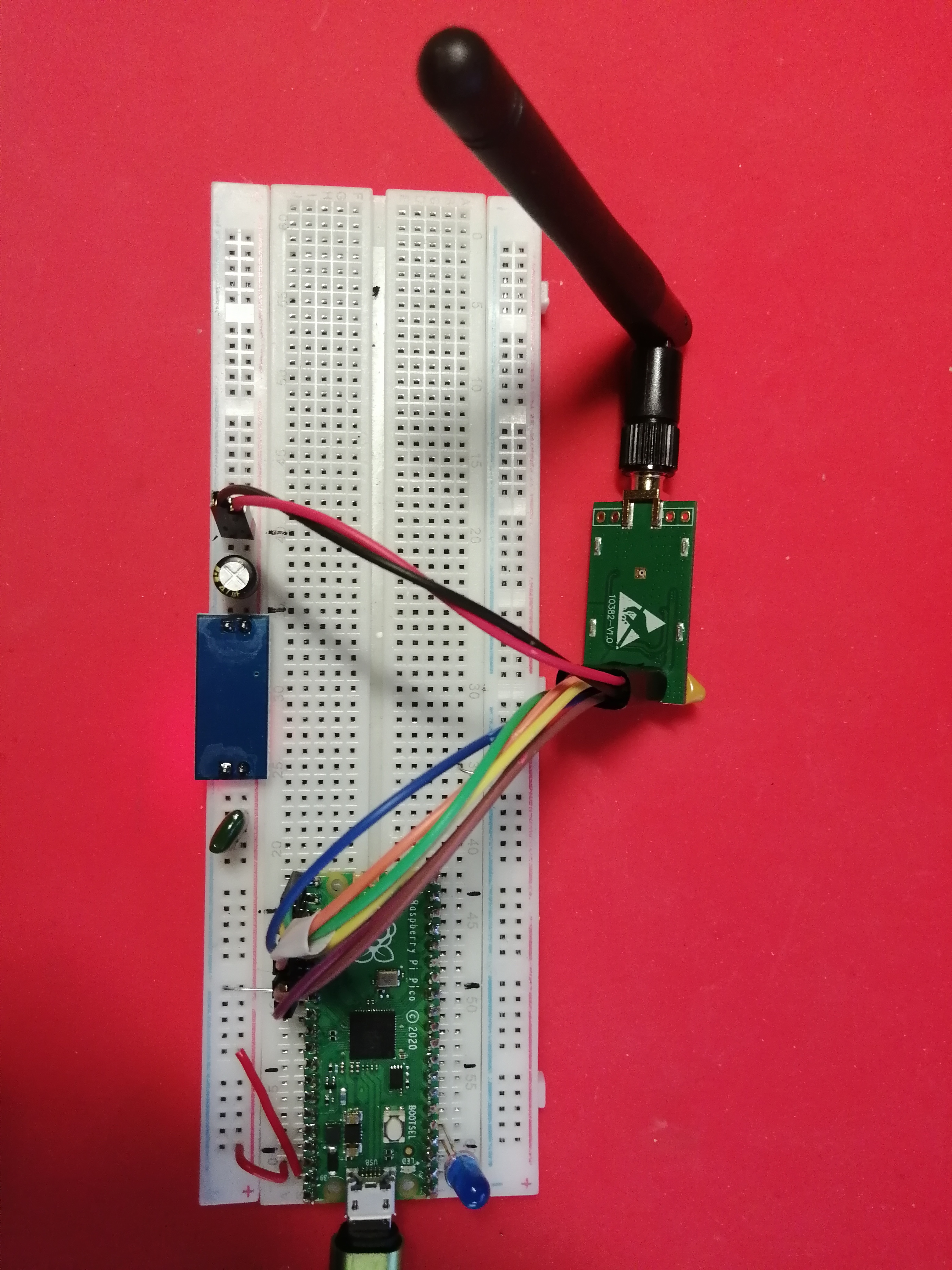
Vysílač
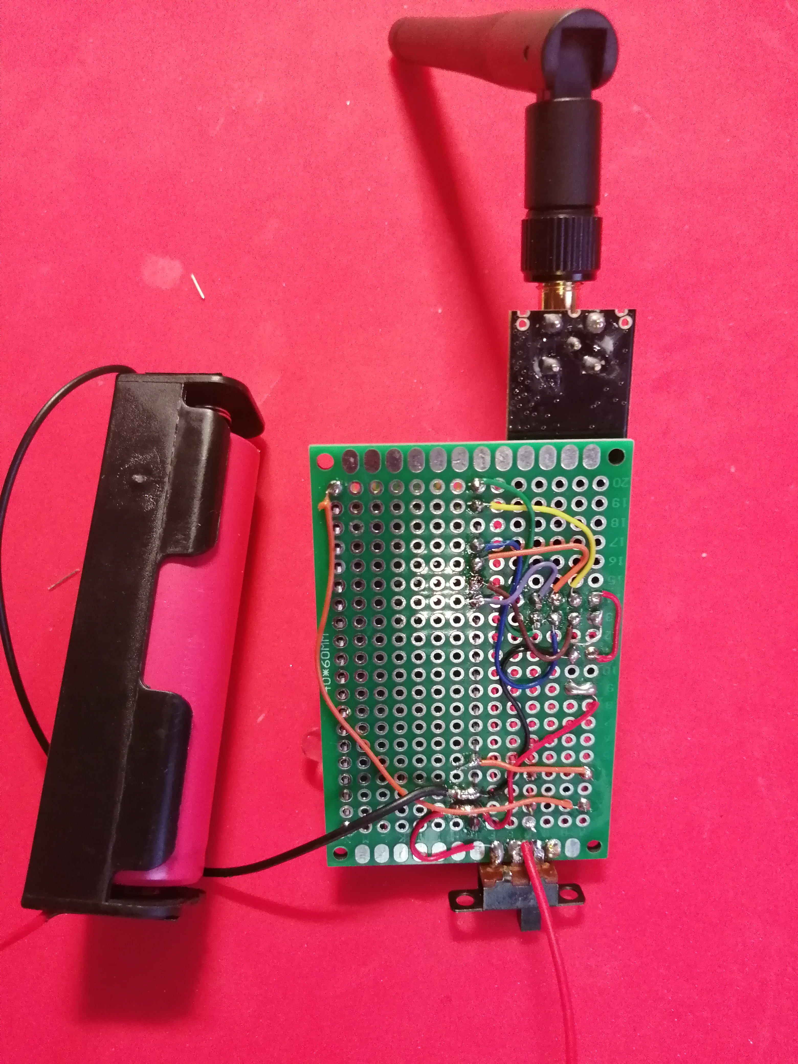
Vysílač

Zdrojové kódy
Vysílač posílá neustále pakety (float) přijímači. Pokud se na vysílači stiskne tlačítko (GPIO15), na přijímači se rozsvítí modrá LED (GPIO2).
Zapojení pinů:
| pin na radiu | GPIO pin na Picu |
|---|---|
V+ (červená) |
3.3V ze zdroje AM1117 (HOLTEK HT7833) nebo 3V3 z Pica |
GND (černá) |
GND |
CSN (žlutá) |
GPIO8 |
CE (hnědá) |
GPIO7 |
MOSI (oranžová) |
GPIO19 |
SCK (modrá) |
GPIO18 |
IRQ (fialová) |
GPIO21 |
MISO (zelená) |
GPIO16 |
examples_pico/transmitter.cpp
/*
 * See documentation at https://nRF24.github.io/RF24
 * See License information at root directory of this library
 * Author: Brendan Doherty (2bndy5)
 */

// vysílač

/**
 * A simple example of sending data from 1 nRF24L01 transceiver to another.
 *
 * This example was written to be used on 2 devices acting as "nodes".
 * Use the Serial Terminal to change each node's behavior.
 */
#include "pico/stdlib.h"  // printf(), sleep_ms(), getchar_timeout_us(), to_us_since_boot(), get_absolute_time()
#include "pico/bootrom.h" // reset_usb_boot()
#include <tusb.h>         // tud_cdc_connected()
#include <RF24.h>         // RF24 radio object
#include "defaultPins.h"  // board presumptive default pin numbers for CE_PIN and CSN_PIN

// instantiate an object for the nRF24L01 transceiver
RF24 radio(CE_PIN, CSN_PIN);

// Used to control whether this node is sending or receiving
bool role = true; // true = TX role, false = RX role

// For this example, we'll be using a payload containing
// a single float number that will be incremented
// on every successful transmission
float payload = 10.0;
#define LED_PIN 2
#define DLED_PIN 25
#define TL_PIN  15
bool stav = true;

bool setup()
{
    // Let these addresses be used for the pair
    uint8_t address[][6] = {"1Node", "2Node"};
    // It is very helpful to think of an address as a path instead of as
    // an identifying device destination

    // to use different addresses on a pair of radios, we need a variable to
    // uniquely identify which address this radio will use to transmit
    bool radioNumber = 0; // 0 uses address[0] to transmit, 1 uses address[1] to transmit

    // wait here until the CDC ACM (serial port emulation) is connected
//    while (!tud_cdc_connected()) {
//        sleep_ms(10);
//    }
    gpio_set_function(LED_PIN,GPIO_FUNC_SIO);
    gpio_set_dir(LED_PIN,GPIO_OUT);
    gpio_put(LED_PIN,1);
    sleep_ms(200);
    gpio_put(LED_PIN,0);
    gpio_set_function(DLED_PIN,GPIO_FUNC_SIO);
    gpio_set_dir(DLED_PIN,GPIO_OUT);
    gpio_put(DLED_PIN,1);
    sleep_ms(200);
    gpio_put(DLED_PIN,0);

    gpio_set_function(TL_PIN,GPIO_FUNC_SIO);
    gpio_set_dir(TL_PIN,GPIO_IN);
    gpio_pull_down(TL_PIN);

    // initialize the transceiver on the SPI bus
    if (!radio.begin()) {
        printf("radio hardware is not responding!!\n");
	gpio_put(DLED_PIN,1);
        return false;
    }
    gpio_put(DLED_PIN,0);

    // print example's introductory prompt
    printf("Vysílač.\n");

    // Set the PA Level low to try preventing power supply related problems
    // because these examples are likely run with nodes in close proximity to
    // each other.
    radio.setPALevel(RF24_PA_LOW); // RF24_PA_MAX is default.

    // Nastavení rychlosti přenosu na 1Mbit/s
    radio.setDataRate(RF24_1MBPS);

    // save on transmission time by setting the radio to only transmit the
    // number of bytes we need to transmit a float
    radio.setPayloadSize(sizeof(payload)); // float datatype occupies 4 bytes

    // set the TX address of the RX node for use on the TX pipe (pipe 0)
    radio.stopListening(address[radioNumber]);

    // set the RX address of the TX node into a RX pipe
    radio.openReadingPipe(1, address[!radioNumber]); // using pipe 1

    // additional setup specific to the node's role
    if (role) {
        radio.stopListening(); // put radio in TX mode
    }
    else {
        radio.startListening(); // put radio in RX mode
    }


    return true;
} // setup

void loop()
{
    if (role) {
        // This device is a TX node

        uint64_t start_timer = to_us_since_boot(get_absolute_time()); // start the timer
        bool report = radio.write(&payload, sizeof(payload));         // transmit & save the report
        uint64_t end_timer = to_us_since_boot(get_absolute_time());   // end the timer

        if (report) {
            // payload was delivered; print the payload sent & the timer result
            // printf("Transmission successful! Time to transmit = %llu us. Sent: %f\n", end_timer - start_timer, payload);
	    gpio_put(LED_PIN,1);
            // increment float payload
            payload += 0.01;
        }
        else {
            // payload was not delivered
            //printf("Transmission failed or timed out\n");
	    gpio_put(LED_PIN,0);
        }

        // to make this example readable in the serial terminal
        sleep_ms(1000); // slow transmissions down by 1 second
	gpio_put(LED_PIN,0);
    }
    else {
        // This device is a RX node

        uint8_t pipe;
        if (radio.available(&pipe)) {               // is there a payload? get the pipe number that received it
            uint8_t bytes = radio.getPayloadSize(); // get the size of the payload
            radio.read(&payload, bytes);            // fetch payload from FIFO
	    if( payload < 1.0) {
		gpio_put(LED_PIN,1);
	    } else {
		gpio_put(LED_PIN,0);
	    }
        }
    } // role
    // tlačítko zmáčknuto
    if( gpio_get(TL_PIN) ) {
	payload = 0.0;
    }

} // loop

int main()
{
    stdio_init_all(); // init necessary IO for the RP2040

    while (!setup()) { // if radio.begin() failed
        // hold program in infinite attempts to initialize radio
    }
    while (true) {
        loop();
    }
    return 0; // we will never reach this
}
examples_pico/receiver.cpp
/*
 * See documentation at https://nRF24.github.io/RF24
 * See License information at root directory of this library
 * Author: Brendan Doherty (2bndy5)
 */

// přijímač

/**
 * A simple example of sending data from 1 nRF24L01 transceiver to another.
 *
 * This example was written to be used on 2 devices acting as "nodes".
 * Use the Serial Terminal to change each node's behavior.
 */
#include "pico/stdlib.h"  // printf(), sleep_ms(), getchar_timeout_us(), to_us_since_boot(), get_absolute_time()
#include "pico/bootrom.h" // reset_usb_boot()
#include <tusb.h>         // tud_cdc_connected()
#include <RF24.h>         // RF24 radio object
#include "defaultPins.h"  // board presumptive default pin numbers for CE_PIN and CSN_PIN

// instantiate an object for the nRF24L01 transceiver
RF24 radio(CE_PIN, CSN_PIN);

// Used to control whether this node is sending or receiving
bool role = false; // true = TX role, false = RX role

// For this example, we'll be using a payload containing
// a single float number that will be incremented
// on every successful transmission
float payload = 0.0;
#define LED_PIN  2
#define TL_PIN  15
#define DLED_PIN 25
bool stav = true;

bool setup()
{
    // Let these addresses be used for the pair
    uint8_t address[][6] = {"1Node", "2Node"};
    // It is very helpful to think of an address as a path instead of as
    // an identifying device destination

    // to use different addresses on a pair of radios, we need a variable to
    // uniquely identify which address this radio will use to transmit
    bool radioNumber = 1; // 0 uses address[0] to transmit, 1 uses address[1] to transmit

    // wait here until the CDC ACM (serial port emulation) is connected
//    while (!tud_cdc_connected()) {
//        sleep_ms(10);
//    }

    gpio_set_function(LED_PIN,GPIO_FUNC_SIO);
    gpio_set_dir(LED_PIN,GPIO_OUT);
    gpio_put(LED_PIN,1);
    sleep_ms(200);
    gpio_put(LED_PIN,0);

    gpio_set_function(DLED_PIN,GPIO_FUNC_SIO);
    gpio_set_dir(DLED_PIN,GPIO_OUT);
    gpio_put(DLED_PIN,1);
    sleep_ms(200);

    gpio_set_function(TL_PIN,GPIO_FUNC_SIO);
    gpio_set_dir(TL_PIN,GPIO_IN);
    gpio_pull_down(TL_PIN);

    // initialize the transceiver on the SPI bus
    if (!radio.begin()) {
        printf("radio hardware is not responding!!\n");
	gpio_put(DLED_PIN,1);
        return false;
    }
    gpio_put(DLED_PIN,0);

    // print example's introductory prompt
    printf("Přijímač.\n");


    // Set the PA Level low to try preventing power supply related problems
    // because these examples are likely run with nodes in close proximity to
    // each other.
    radio.setPALevel(RF24_PA_LOW); // RF24_PA_MAX is default.
    // Nastavení rychlosti přenosu na 1Mbit/s
    radio.setDataRate(RF24_1MBPS);

    // save on transmission time by setting the radio to only transmit the
    // number of bytes we need to transmit a float
    radio.setPayloadSize(sizeof(payload)); // float datatype occupies 4 bytes

    // set the TX address of the RX node for use on the TX pipe (pipe 0)
    radio.stopListening(address[radioNumber]);

    // set the RX address of the TX node into a RX pipe
    radio.openReadingPipe(1, address[!radioNumber]); // using pipe 1

    // additional setup specific to the node's role
    if (role) {
        radio.stopListening(); // put radio in TX mode
    }
    else {
        radio.startListening(); // put radio in RX mode
    }


    return true;
} // setup

void loop()
{
    if (role) {
        // This device is a TX node

        uint64_t start_timer = to_us_since_boot(get_absolute_time()); // start the timer
        bool report = radio.write(&payload, sizeof(payload));         // transmit & save the report
        uint64_t end_timer = to_us_since_boot(get_absolute_time());   // end the timer

        if (report) {
            // payload was delivered; print the payload sent & the timer result
            // printf("Transmission successful! Time to transmit = %llu us. Sent: %f\n", end_timer - start_timer, payload);
	    gpio_put(LED_PIN,1);
            // increment float payload
            payload += 0.01;
        }
        else {
            // payload was not delivered
            //printf("Transmission failed or timed out\n");
	    gpio_put(LED_PIN,0);
        }

        // to make this example readable in the serial terminal
        sleep_ms(1000); // slow transmissions down by 1 second
	gpio_put(LED_PIN,0);
    }
    else {
        // This device is a RX node

        uint8_t pipe;
        if (radio.available(&pipe)) {               // is there a payload? get the pipe number that received it
            uint8_t bytes = radio.getPayloadSize(); // get the size of the payload
            radio.read(&payload, bytes);            // fetch payload from FIFO
	    if( payload < 0.2) {
		gpio_put(LED_PIN,1);
	    } else {
		gpio_put(LED_PIN,0);
	    }
        }
    } // role
    if( gpio_get(TL_PIN) ) {
	payload = 0.0;
    }

} // loop

int main()
{
    stdio_init_all(); // init necessary IO for the RP2040

    while (!setup()) { // if radio.begin() failed
        // hold program in infinite attempts to initialize radio
    }
    while (true) {
        loop();
    }
    return 0; // we will never reach this
}
Nastavení pinů:
examples_pico/defaultPins.h
// pre-chosen pins for different boards
#ifndef DEFAULTPINS_H
#define DEFAULTPINS_H

#if defined(ADAFRUIT_QTPY_RP2040)
    // for this board, you can still use the Stemma QT connector as a separate I2C bus (`i2c1`)
    #define CE_PIN  PICO_DEFAULT_I2C_SDA_PIN // the pin labeled SDA
    #define CSN_PIN PICO_DEFAULT_I2C_SCL_PIN // the pin labeled SCL
    #define IRQ_PIN PICO_DEFAULT_UART_RX_PIN // the pin labeled RX

#elif defined(PIMORONI_TINY2040)
    // default SPI_SCK_PIN = 6
    // default SPI_TX_PIN = 7
    // default SPI_RX_PIN = 4
    #define CE_PIN  PICO_DEFAULT_I2C_SCL_PIN // pin 3
    #define CSN_PIN PICO_DEFAULT_SPI_CSN_PIN // pin 5
    #define IRQ_PIN PICO_DEFAULT_I2C_SDA_PIN // pin 2

#elif defined(SPARFUN_THINGPLUS)
    #define CSN_PIN 16 // the pin labeled 16
    #define CE_PIN  7  // the pin labeled SCL
    #define IRQ_PIN 6  // the pin labeled SDA

#else
    // pins available on (ADAFRUIT_ITSYBITSY_RP2040 || ADAFRUIT_FEATHER_RP2040 || Pico_board || Sparkfun_ProMicro || SparkFun MicroMod)

    #define CE_PIN  20
    #define CSN_PIN 17
    #define IRQ_PIN 21
#endif // board detection macro defs

#endif // DEFAULTPINS_H
examples_pico/CMakeLists.txt
cmake_minimum_required(VERSION 3.12)

# Pull in SDK (must be before project)
include(../cmake/pico_sdk_import.cmake)

# generate a compilation database for static analysis by clang-tidy
set(CMAKE_EXPORT_COMPILE_COMMANDS ON)

project(pico_examples C CXX ASM)

# Initialize the Pico SDK
pico_sdk_init()

# In YOUR project, include RF24's CMakeLists.txt
# giving the path depending on where the library
# is cloned to in your project
include(../CMakeLists.txt)

# iterate over a list of examples by name
set(EXAMPLES_LIST
    gettingStarted
    transmitter
    receiver
    acknowledgementPayloads
    streamingData
    manualAcknowledgements
    multiceiverDemo
    interruptConfigure
    scanner
)

foreach(example ${EXAMPLES_LIST})
    # make a target
    add_executable(${example} ${example}.cpp defaultPins.h)

    # link the necessary libs to the target
    target_link_libraries(${example} PUBLIC
        RF24
        pico_stdlib
        hardware_spi
        hardware_gpio
    )

    # specify USB port as default serial communication's interface (not UART RX/TX pins)
    pico_enable_stdio_usb(${example} 1)
    pico_enable_stdio_uart(${example} 0)

    # create map/bin/hex file etc.
    pico_add_extra_outputs(${example})
endforeach()
Sestavení programu
git clone https://github.com/nRF24/RF24
cd RF24
mkdir build
cd build
cmake ../examples_pico/ -DCMAKE_BUILD_TYPE=Release -DPICO_BOARD=pico
make -j8
Celý projekt
Zdroje a odkazy
Bezdrátový modul nRF24L01p+ PA+ LNA 2.4GHz na vysílači
Bezdrátový modul nRF24L01+ 2.4GHz s malým dosahem (na scanneru)